ZHCSBK0D October   2012  – October 2015 F28M36H33B2 , F28M36H53B2 , F28M36P53C2 , F28M36P63C2

PRODUCTION DATA.  

  1. 1器件概述
    1. 1.1 特性
    2. 1.2 应用
    3. 1.3 描述
    4. 1.4 功能方框图
  2. 2修订历史记录
  3. 3Device Comparison
  4. 4Terminal Configuration and Functions
    1. 4.1 Pin Diagrams
    2. 4.2 Signal Descriptions
  5. 5Specifications
    1. 5.1  Absolute Maximum Ratings
    2. 5.2  ESD Ratings
    3. 5.3  Recommended Operating Conditions
    4. 5.4  Electrical Characteristics
    5. 5.5  Power Consumption Summary
    6. 5.6  Thermal Resistance Characteristics for ZWT Package (Revision 0 Silicon)
    7. 5.7  Thermal Resistance Characteristics for ZWT Package (Revision A Silicon)
    8. 5.8  Thermal Design Considerations
    9. 5.9  Timing and Switching Characteristics
      1. 5.9.1 Power Sequencing
        1. 5.9.1.1 Power Management and Supervisory Circuit Solutions
      2. 5.9.2 Clock Specifications
        1. 5.9.2.1 Changing the Frequency of the Main PLL
        2. 5.9.2.2 Input Clock Frequency and Timing Requirements, PLL Lock Times
        3. 5.9.2.3 Output Clock Frequency and Switching Characteristics
        4. 5.9.2.4 Internal Clock Frequencies
      3. 5.9.3 Timing Parameter Symbology
        1. 5.9.3.1 General Notes on Timing Parameters
        2. 5.9.3.2 Test Load Circuit
      4. 5.9.4 Flash Timing - Master Subsystem
      5. 5.9.5 Flash Timing - Control Subsystem
      6. 5.9.6 GPIO Electrical Data and Timing
        1. 5.9.6.1 GPIO - Output Timing
        2. 5.9.6.2 GPIO - Input Timing
        3. 5.9.6.3 Sampling Window Width for Input Signals
        4. 5.9.6.4 Low-Power Mode Wakeup Timing
      7. 5.9.7 External Interrupt Electrical Data and Timing
    10. 5.10 Analog and Shared Peripherals
      1. 5.10.1 Analog-to-Digital Converter
        1. 5.10.1.1 Sample Mode
        2. 5.10.1.2 Start-of-Conversion Triggers
        3. 5.10.1.3 Analog Inputs
        4. 5.10.1.4 ADC Result Registers and EOC Interrupts
        5. 5.10.1.5 ADC Electrical Data and Timing
      2. 5.10.2 Comparator + DAC Units
        1. 5.10.2.1 On-Chip Comparator and DAC Electrical Data and Timing
      3. 5.10.3 Interprocessor Communications
      4. 5.10.4 External Peripheral Interface
        1. 5.10.4.1 EPI General-Purpose Mode
        2. 5.10.4.2 EPI SDRAM Mode
        3. 5.10.4.3 EPI Host Bus Mode
          1. 5.10.4.3.1 EPI 8-Bit Host Bus (HB-8) Mode
            1. 5.10.4.3.1.1 HB-8 Muxed Address/Data Mode
            2. 5.10.4.3.1.2 HB-8 Non-Muxed Address/Data Mode
            3. 5.10.4.3.1.3 HB-8 FIFO Mode
          2. 5.10.4.3.2 EPI 16-Bit Host Bus (HB-16) Mode
            1. 5.10.4.3.2.1 HB-16 Muxed Address/Data Mode
            2. 5.10.4.3.2.2 HB-16 Non-Muxed Address/Data Mode
            3. 5.10.4.3.2.3 HB-16 FIFO Mode
        4. 5.10.4.4 EPI Electrical Data and Timing
    11. 5.11 Master Subsystem Peripherals
      1. 5.11.1 Synchronous Serial Interface
        1. 5.11.1.1 Bit Rate Generation
        2. 5.11.1.2 Transmit FIFO
        3. 5.11.1.3 Receive FIFO
        4. 5.11.1.4 Interrupts
        5. 5.11.1.5 Frame Formats
      2. 5.11.2 Universal Asynchronous Receiver/Transmitter
        1. 5.11.2.1 Baud-Rate Generation
        2. 5.11.2.2 Transmit and Receive Logic
        3. 5.11.2.3 Data Transmission and Reception
        4. 5.11.2.4 Interrupts
      3. 5.11.3 Cortex-M3 Inter-Integrated Circuit
        1. 5.11.3.1 Functional Overview
        2. 5.11.3.2 Available Speed Modes
        3. 5.11.3.3 I2C Electrical Data and Timing
      4. 5.11.4 Cortex-M3 Controller Area Network
        1. 5.11.4.1 Functional Overview
      5. 5.11.5 Cortex-M3 Universal Serial Bus Controller
        1. 5.11.5.1 Functional Description
      6. 5.11.6 Cortex-M3 Ethernet Media Access Controller
        1. 5.11.6.1 Functional Overview
        2. 5.11.6.2 MII Signals
        3. 5.11.6.3 EMAC Electrical Data and Timing
        4. 5.11.6.4 MDIO Electrical Data and Timing
    12. 5.12 Control Subsystem Peripherals
      1. 5.12.1 High-Resolution PWM and Enhanced PWM Modules
        1. 5.12.1.1 HRPWM Electrical Data and Timing
        2. 5.12.1.2 ePWM Electrical Data and Timing
          1. 5.12.1.2.1 Trip-Zone Input Timing
      2. 5.12.2 Enhanced Capture Module
        1. 5.12.2.1 eCAP Electrical Data and Timing
      3. 5.12.3 Enhanced Quadrature Encoder Pulse Module
        1. 5.12.3.1 eQEP Electrical Data and Timing
      4. 5.12.4 C28x Inter-Integrated Circuit Module
        1. 5.12.4.1 Functional Overview
        2. 5.12.4.2 Clock Generation
        3. 5.12.4.3 I2C Electrical Data and Timing
      5. 5.12.5 C28x Serial Communications Interface
        1. 5.12.5.1 Architecture
        2. 5.12.5.2 Multiprocessor and Asynchronous Communication Modes
      6. 5.12.6 C28x Serial Peripheral Interface
        1. 5.12.6.1 Functional Overview
        2. 5.12.6.2 SPI Electrical Data and Timing
          1. 5.12.6.2.1 Master Mode Timing
          2. 5.12.6.2.2 SPI Slave Mode Timing
      7. 5.12.7 C28x Multichannel Buffered Serial Port
        1. 5.12.7.1 McBSP Electrical Data and Timing
          1. 5.12.7.1.1 McBSP Transmit and Receive Timing
          2. 5.12.7.1.2 McBSP as SPI Master or Slave Timing
  6. 6Detailed Description
    1. 6.1  Memory Maps
      1. 6.1.1 Control Subsystem Memory Map
      2. 6.1.2 Master Subsystem Memory Map
    2. 6.2  Identification
    3. 6.3  Master Subsystem
      1. 6.3.1 Cortex-M3 CPU
      2. 6.3.2 Cortex-M3 DMA and NVIC
      3. 6.3.3 Cortex-M3 Interrupts
      4. 6.3.4 Cortex-M3 Vector Table
      5. 6.3.5 Cortex-M3 Local Peripherals
      6. 6.3.6 Cortex-M3 Local Memory
      7. 6.3.7 Cortex-M3 Accessing Shared Resources and Analog Peripherals
    4. 6.4  Control Subsystem
      1. 6.4.1 C28x CPU/FPU/VCU
      2. 6.4.2 C28x Core Hardware Built-In Self-Test
      3. 6.4.3 C28x Peripheral Interrupt Expansion
      4. 6.4.4 C28x Direct Memory Access
      5. 6.4.5 C28x Local Peripherals
      6. 6.4.6 C28x Local Memory
      7. 6.4.7 C28x Accessing Shared Resources and Analog Peripherals
    5. 6.5  Analog Subsystem
      1. 6.5.1 ADC1
      2. 6.5.2 ADC2
      3. 6.5.3 Analog Comparator + DAC
      4. 6.5.4 Analog Common Interface Bus
    6. 6.6  Master Subsystem NMIs
    7. 6.7  Control Subsystem NMIs
    8. 6.8  Resets
      1. 6.8.1 Cortex-M3 Resets
      2. 6.8.2 C28x Resets
      3. 6.8.3 Analog Subsystem and Shared Resources Resets
      4. 6.8.4 Device Boot Sequence
    9. 6.9  Internal Voltage Regulation and Power-On-Reset Functionality
      1. 6.9.1 Analog Subsystem's Internal 1.8-V VREG
      2. 6.9.2 Digital Subsystem's Internal 1.2-V VREG
      3. 6.9.3 Analog and Digital Subsystems' Power-On-Reset Functionality
      4. 6.9.4 Connecting ARS and XRS Pins
    10. 6.10 Input Clocks and PLLs
      1. 6.10.1 Internal Oscillator (Zero-Pin)
      2. 6.10.2 Crystal Oscillator/Resonator (Pins X1/X2 and VSSOSC)
      3. 6.10.3 External Oscillators (Pins X1, VSSOSC, XCLKIN)
      4. 6.10.4 Main PLL
      5. 6.10.5 USB PLL
    11. 6.11 Master Subsystem Clocking
      1. 6.11.1 Cortex-M3 Run Mode
      2. 6.11.2 Cortex-M3 Sleep Mode
      3. 6.11.3 Cortex-M3 Deep Sleep Mode
    12. 6.12 Control Subsystem Clocking
      1. 6.12.1 C28x Normal Mode
      2. 6.12.2 C28x IDLE Mode
      3. 6.12.3 C28x STANDBY Mode
    13. 6.13 Analog Subsystem Clocking
    14. 6.14 Shared Resources Clocking
    15. 6.15 Loss of Input Clock (NMI Watchdog Function)
    16. 6.16 GPIOs and Other Pins
      1. 6.16.1 GPIO_MUX1
      2. 6.16.2 GPIO_MUX2
      3. 6.16.3 AIO_MUX1
      4. 6.16.4 AIO_MUX2
    17. 6.17 Emulation/JTAG
    18. 6.18 Code Security Module
      1. 6.18.1 Functional Description
    19. 6.19 µCRC Module
      1. 6.19.1 Functional Description
      2. 6.19.2 CRC Polynomials
      3. 6.19.3 CRC Calculation Procedure
      4. 6.19.4 CRC Calculation for Data Stored In Secure Memory
  7. 7Applications, Implementation, and Layout
    1. 7.1 Development Tools
      1. 7.1.1 H63C2 Concerto Experimenter Kit
      2. 7.1.2 F28M36 Concerto Control Card
    2. 7.2 Software Tools
      1. 7.2.1 controlSUITE
      2. 7.2.2 Code Composer Studio (CCS) Integrated Development Environment (IDE)
      3. 7.2.3 F021 Flash Application Programming Interface (API)
    3. 7.3 Training
  8. 8器件和文档支持
    1. 8.1 器件支持
      1. 8.1.1 开发支持
      2. 8.1.2 器件和开发支持工具命名规则
    2. 8.2 文档支持
      1. 8.2.1 相关文档
      2. 8.2.2 接收文档更新通知
    3. 8.3 相关链接
    4. 8.4 社区资源
    5. 8.5 商标
    6. 8.6 静电放电警告
    7. 8.7 Glossary
  9. 9机械、封装和可订购信息
    1. 9.1 封装信息

封装选项

请参考 PDF 数据表获取器件具体的封装图。

机械数据 (封装 | 引脚)
  • ZWT|289
散热焊盘机械数据 (封装 | 引脚)
订购信息

1 器件概述

Section 1.1

1.1 特性

  • 主控子系统 — ARM® Cortex®-M3
    • 125MHz
    • 嵌入式存储器
      • 高达 1MB 闪存(纠错码 (ECC))
      • 高达 128KB RAM(ECC 或奇偶校验)
      • 高达 64KB 共享 RAM
      • 2KB 处理器间通信 (IPC) 消息 RAM
    • 五个通用异步收发器 (UART)
    • 四个同步串行接口 (SSI)
      和一个串行外设接口 (SPI)
    • 两个内部集成电路 (I2C)
    • 通用串行总线如影随形 (USB-OTG) + 物理层 (PHY)
    • 10/100 以太网 (ENET) 1588 介质独立接口 (MII)
    • 两个控制器局域网 (D_CAN) 模块(引脚可引导)
    • 32 通道微直接内存访问 (µDMA)
    • 双重安全区域(每个区域 128 位密码)
    • 外设接口 (EPI)
    • 微循环冗余检验 (µCRC) 模块
    • 四个通用定时器
    • 两个看门狗定时器模块
    • 字节序:小端序
  • 计时
    • 片上晶振振荡器和外部时钟输入
    • 支持动态锁相环 (PLL) 比率变化
  • 1.2V 数字、1.8V 模拟、3.3V I/O 设计
  • 处理器间通信 (IPC)
    • 32 个握手通道
    • 四条通道生成 IPC 中断
    • 可用于通过 IPC 消息 RAM 协调数据传输
  • 多达 142 个独立可编程、复用通用输入/输出 (GPIO) 引脚
    • 无毛刺脉冲 I/O
  • 控制子系统 - TMS320C28x 32 位 CPU
    • 150MHz
    • C28x 内核硬件内置自检
    • 嵌入式存储器
      • 高达 512KB 闪存(纠错码 (ECC))
      • 高达 36KB RAM(ECC 或奇偶校验)
      • 高达 64KB 共享 RAM
      • 2KB 处理器间通信 (IPC) 消息 RAM
    • IEEE-754 单精度浮点单元 (FPU)
    • Viterbi,复杂数学运算,循环冗余校验 (CRC) 单元 (VCU)
    • 串行通信接口 (SCI)
    • SPI
    • I2C
    • 6 通道直接内存访问(DMA)
    • 12 个增强型脉宽调制器 (ePWM) 模块
      • 24 个输出(16 个为高分辨率)
    • 6 个 32 位增强型捕捉 (eCAP) 模块
    • 3 个 32 位增强型正交编码器脉冲 (eQEP) 模块
    • 多通道缓冲串行端口 (McBSP)
    • EPI
    • 一个安全区域(128 位密码)
    • 三个 32 位定时器
    • 字节序:小端序
  • 模拟子系统
    • 双 12 位模数转换器 (ADC)
    • 高达 2.88MSPS
    • 高达 24 个通道
    • 四个采样与保持 (S/H) 电路
    • 多达六个具有 10 位数模转换器 (DAC) 的比较器
  • 封装
    • 289 焊球 ZWT 全新细间距球栅阵列 (nFBGA)
  • 温度选项:
    • T:-40ºC 至 105ºC(结温)
    • S:–40ºC 到 125ºC(结温)
    • Q:–40ºC 到 125ºC(自然通风)
      (针对汽车应用的 Q100 认证)

1.3 描述

Concerto 系列是一款多内核片上系统微控制器单元 (MCU),此控制器具有独立的通信和实时控制子系统。F28M36x 系列器件是 Concerto 产品的第二系列产品。

通信子系统基于符合行业标准的 32 位 ARM Cortex-M3 CPU,并且 具备 多种通信外设(包括以太网 1588、带有 PHY 的 USB OTG、控制器局域网 (CAN)、UART、SSI、I2C)以及一个外部接口。

实时控制子系统基于行业领先的 TI 专有 32 位 C28x 浮点 CPU,并且 具备 最为灵活而又高度精确的控制外设,其中包括具有故障保护功能的 ePWM、编码器和捕捉单元 - 全部由 TI 的 TMS320C2000™ Piccolo™和 Delfino™系列产品来执行。此外,C28-CPU 已得到增强,新增 VCU 指令加速器,能够实现高效的 Viterbi、复杂算术运算、16 位快速傅里叶变换 (FFT) 以及循环冗余校验 (CRC) 算法。

共享一个高速模拟子系统和补充 RAM 内存,还有片上电压稳压和冗余计时电路。安全考虑还包括纠错码 (ECC),奇偶校验和代码安全内存,以及辅助系统级工业安全认证的文档。

器件信息(1)

产品型号 封装 封装尺寸
F28M36P63C2ZWT nFBGA (289) 16.0mm x 16.0mm
F28M36P53C2ZWT nFBGA (289) 16.0mm x 16.0mm
F28M36H53C2ZWT nFBGA (289) 16.0mm x 16.0mm
F28M36H33C2ZWT nFBGA (289) 16.0mm x 16.0mm
(1) 有关这些器件的更多信息,请参见Section 9,机械封装和可订购信息。

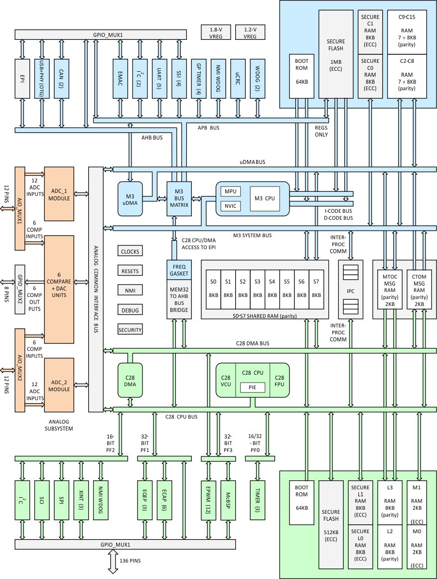
1.4 功能方框图

F28M36P63C2 F28M36P53C2 F28M36H53C2 F28M36H53B2 F28M36H33C2 F28M36H33B2 fbd_prs820.gif Figure 1-1 功能框图