ZHCSBO8A September 2013 – March 2014 DS125BR401A
PRODUCTION DATA.
- 1 特性
- 2 应用范围
- 3 说明
- 4 修订历史记录
- 5 Terminal Configuration and Functions
- 6 Specifications
- 7 Detailed Description
- 8 Applications and Implementation
- 9 Power Supply Recommendations
- 10Layout
- 11器件和文档支持
- 12机械封装和可订购信息
8 Applications and Implementation
8.1 Application Information
8.1.1 Signal Integrity in SAS-3 Applications
SAS-3 specifications have fully specified Rx-Tx training as a means to establish and optimize signal conditioning settings at the 12.0 Gbps data-rate. The DS125BR401A works to extend the reach possible by adding active linear equalization to the channel, boosting attenuated signals so that they can be more easily recovered at the SAS-3 Rx. The A-Channel outputs are specially designed to be transparent to TX FIR signaling passing this information critical for optimal link training to the SAS-3 Rx. The A-Channel device settings used in a SAS-3 environment are EQ = Level 4, DEMA1 = 1 and DEMA0 = 0 in Terminal mode or EQ = 03'h, VOD = 111'b, and DEM = 000'b in SMBus mode.
8.1.2 RX-Detect in SAS/SATA Applications
Unlike PCIe systems, SAS/SATA systems use a low speed Out-Of-Band or OOB communications sequence to detect and communicate between SAS Controllers/Expanders and target drives. This communication eliminates the need to detect for endpoints like PCIe. For SAS systems, it is recommended to tie the RXDET Terminal high. This will ensure any OOB sequences sent from the Controller/Expander will reach the target drive without any additional latency due to the termination detection sequence defined by PCIe.
8.1.3 Signal Integrity in PCIe Applications
When using the DS125BR401A in PCIe GEN-3 systems, there are specific signal integrity settings to ensure signal integrity margin. The settings were optimized by system bench testing. Please contact your field representative for more information regarding the testing completed to achieve these settings.
For tuning the in the downstream direction (from CPU to EP).
- EQB: use the guidelines outlined in Table 5 and Table 6.
- EQA: EQ = 11'b or EQA0 = 1.
- DEMB: Use the guidelines outlined in Table 7.
- DEMA set to 000'b in SMBus Mode.
- VODB: use the guidelines outlined in Table 7.
- VODA: SMBus = 111'b, Terminal Control: DEMA1=1, DEMA0 = 0
For tuning in the upstream direction (from EP to CPU).
- B-Channel:
- A-Channel:
- EQ = 11'b or EQA0 = 1.
- DEM for trace lengths < 15in set to 000'b in SMBus Mode.
- DEM for trace lengths > 15in set to 000'b in SMBus Mode.
- VOD: SMBus = 111'b, Terminal Control: DEMA1=1, DEMA0 = 0
8.1.4 MODE operation with SMBus Registers
When in SMBus mode (Slave or Master), the MODE Terminal retains control of the output driver characteristics. In order to override this control function, Register 0x08[2] must be written with a "1". Writing this bit enables MODE control of each channel individually using the channel registers defined in Table 12.
8.2 Typical Application
SAS-3 specifications have fully specified Rx-Tx training as a means to establish and optimize signal conditioning settings at the 12.0 Gbps data-rate. The DS125BR401A works to extend the reach possible by adding active linear equalization to the channel, boosting attenuated signals so that they can be more easily recovered at the SAS-3 Rx. The A-Channel outputs are specially designed to be transparent to TX FIR signaling passing this information critical for optimal link training to the SAS-3 Rx. The A-Channel device settings used in a SAS-3 environment are EQ = Level 4, DEMA1 = 1 and DEMA0 = 0 in Terminal mode or EQ = 03'h, VOD = 111'b, and DEM = 000'b in SMBus mode.
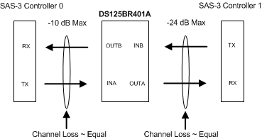 Figure 8. Typical System Configuration
8.2.1 Design Requirements
As with any high speed design, there are many factors which influence the overall performance, this section lists some critical areas for consideration and study.
- Limit the maximum losses according to Figure 8.
- Utilize 100Ω impedance traces. Generally these are very loosely coupled to ease routing length differences.
- Place AC-coupling capacitors near to the receiver end of each channel segment to minimize reflections.
- The maximum body size for AC-coupling capacitors is 0402.
- Back-drill connector vias and signal vias to minimize stub length
- Use Reference plane vias to ensure a low inductance path for the return current.
8.2.2 Detailed Design Procedure
The DS125BR401A is designed to be placed at an offset location with respect to the overall channel attenuation, a maximum attenuation of 10 dB on the INA side and 22 dB on the INB side. The input channel segment with the lowest attenuation should always be connected to the INA port. This drives different design constraints and settings to the A-Channel and B-Channel sides. The A-Channel device settings used in a SAS-3 environment are EQ = Level 4, DEMA1 = 1 and DEMA0 = 0 in Terminal mode or EQ = 03'h, VOD = 111'b, and DEM = 000'b in SMBus mode. This setting has proven to give the best overall SAS-3 extension for all configurations tested. The B-Channel has a larger signal gain than the A-Channel and the capability to add even higher levels of CTLE if required. In even the longer channel configurations with attenuation on the B-Channel inputs of ~ 20 dB @ 6 GHx can recover a solid eye opening with EQB = Level 1, DEMA1 = FLOAT and DEMA0 = R in Terminal mode or EQ = 00'h, VOD = 101'b, and DEM = 000'b in SMBus mode.
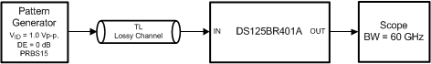 Figure 9. Test Setup Connections Diagram
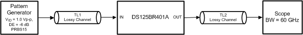 Figure 10. Test Setup Connections Diagram
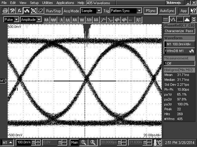
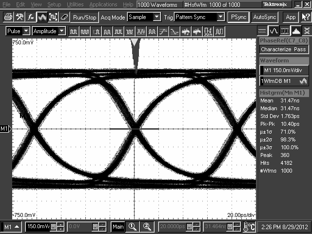
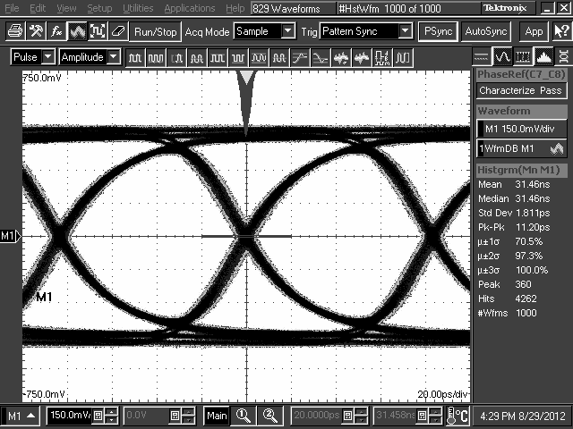
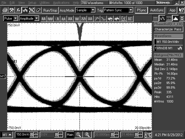
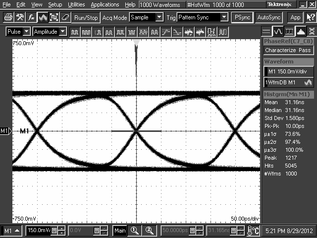
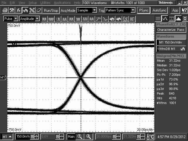
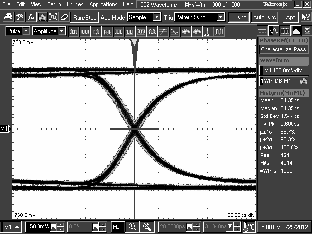
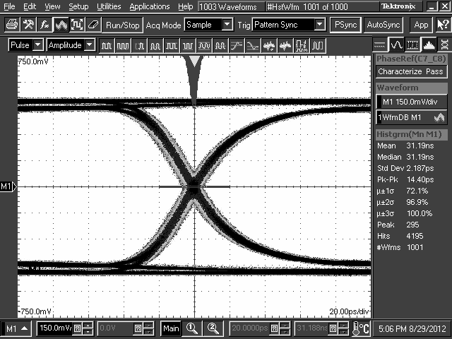
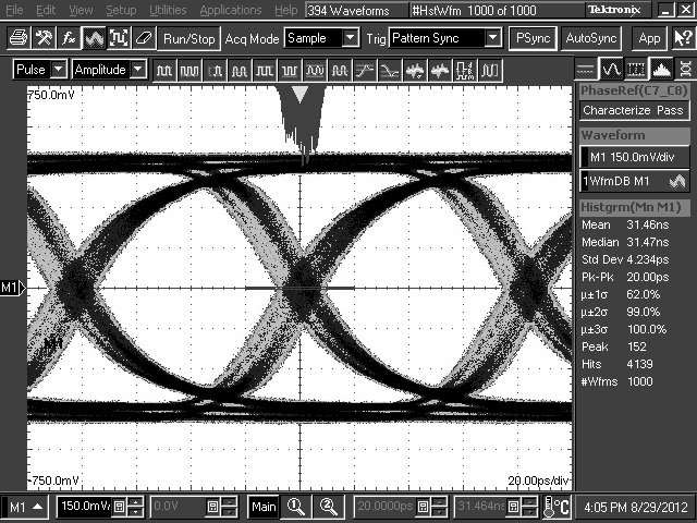
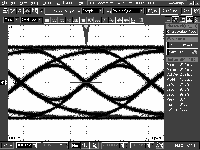
8.2.3 Application Performance Plots