ZHCSEJ8B January 2011 – December 2015
PRODUCTION DATA.
- 1 特性
- 2 应用
- 3 说明
- 4 修订历史记录
- 5 说明 (续)
- 6 Pin Configuration and Functions
-
7 Specifications
- 7.1 Absolute Maximum Ratings
- 7.2 ESD Ratings
- 7.3 Recommended Operating Conditions
- 7.4 Thermal Information
- 7.5 Electrical Characteristics: General Purpose I/O
- 7.6 Supply Current
- 7.7 REG27 LDO
- 7.8 Coulomb Counter
- 7.9 ADC
- 7.10 External Capacitor Voltage Balance Drive
- 7.11 Capacitor Voltage Monitor
- 7.12 Internal Temperature Sensor
- 7.13 Thermistor Measurement Support
- 7.14 Internal Thermal Shutdown
- 7.15 High-Frequency Oscillator
- 7.16 Low-Frequency Oscillator
- 7.17 RAM Backup
- 7.18 Flash
- 7.19 Current Protection Thresholds
- 7.20 Current Protection Timing
- 7.21 Timing Requirements: SMBus
- 7.22 Typical Characteristics
-
8 Detailed Description
- 8.1 Overview
- 8.2 Functional Block Diagram
- 8.3
Feature Description
- 8.3.1 Capacitance Monitoring and Learning
- 8.3.2 Capacitor Voltage Balancing
- 8.3.3 Charge Control
- 8.3.4 Lifetime Data Gathering
- 8.3.5
Safety Detection Features
- 8.3.5.1 Capacitor Overvoltage (OV)
- 8.3.5.2 Capacitor Voltage Imbalance (CIM)
- 8.3.5.3 Weak Capacitor (CLBAD)
- 8.3.5.4 Overtemperature (OT)
- 8.3.5.5 Overcurrent During Charging (OC Chg)
- 8.3.5.6 Overcurrent During Discharging (OC Dsg)
- 8.3.5.7 Short-Circuit During Charging (SC Chg)
- 8.3.5.8 Short-Circuit During Discharging (SC Dsg)
- 8.3.5.9 AFE Watchdog (WDF)
- 8.3.5.10 Integrated AFE Communication Fault (AFE_C)
- 8.3.5.11 Data Flash Fault (DFF)
- 8.3.5.12 FAULT Indication (FAULT Pin)
- 8.3.6 Communications
- 8.3.7 Security (Enables and Disables Features)
- 8.3.8
Measurement System Calibration
- 8.3.8.1 Coulomb Counter Deadband
- 8.3.8.2 Auto Calibration
- 8.3.8.3 Current Gain
- 8.3.8.4 CC Delta
- 8.3.8.5 Cap1 K-factor
- 8.3.8.6 Cap2 K-factor
- 8.3.8.7 Cap3 K-factor
- 8.3.8.8 Cap4 K-factor
- 8.3.8.9 Cap5 K-factor
- 8.3.8.10 K-factor Override Flag
- 8.3.8.11 System Voltage K-factor
- 8.3.8.12 Stack Voltage K-factor
- 8.3.8.13 K-factor Stack Override Flag
- 8.3.8.14 CC Offset
- 8.3.8.15 Board Offset
- 8.3.8.16 Int Temp Offset
- 8.3.8.17 Ext1 Temp Offset
- 8.3.8.18 CC Current
- 8.3.8.19 Voltage Signal
- 8.3.8.20 Temp Signal
- 8.3.8.21 CC Offset Time
- 8.3.8.22 ADC Offset Time
- 8.3.8.23 Current Gain Time
- 8.3.8.24 Voltage Time
- 8.3.8.25 Temperature Time
- 8.3.8.26 Cal Mode Timeout
- 8.3.8.27 Ext Coef a1..a5, b1..b4, Ext rc0, Ext adc0
- 8.3.8.28 Rpad
- 8.3.8.29 Rint
- 8.3.8.30 Int Coef 1..4, Int Min AD, Int Max Temp
- 8.3.8.31 Filter
- 8.3.8.32 Deadband
- 8.3.8.33 CC Deadband
- 8.4 Device Functional Modes
- 8.5
Programming
- 8.5.1 Communications
- 8.5.2
SBS Commands
- 8.5.2.1 SBS Command Summary
- 8.5.2.2
SBS Command Details
- 8.5.2.2.1
ManufacturerAccess (0x00)
- 8.5.2.2.1.1 Device Type (0x0001)
- 8.5.2.2.1.2 Firmware Version (0x0002)
- 8.5.2.2.1.3 Hardware Version (0x0003)
- 8.5.2.2.1.4 DF Checksum (0x0004)
- 8.5.2.2.1.5 Seal Device (0x0020)
- 8.5.2.2.1.6 Lifetime and Capacitor Balancing Enable (0x0021)
- 8.5.2.2.1.7 FAULT Activation (0x0030)
- 8.5.2.2.1.8 FAULT Clear (0x0031)
- 8.5.2.2.1.9 CHGLVL0 Activation (0x0032)
- 8.5.2.2.1.10 CHGLVL0 Clear (0x0033)
- 8.5.2.2.1.11 CHGLVL1 Activation (0x0033)
- 8.5.2.2.1.12 CHGLVL1 Clear (0x0034)
- 8.5.2.2.1.13 Learn Load Activation (0x0037)
- 8.5.2.2.1.14 Learn Load Clear (0x0038)
- 8.5.2.2.1.15 Calibration Mode (0x0040)
- 8.5.2.2.1.16 Reset (0x0041)
- 8.5.2.2.1.17 Unseal Device (UnsealKey)
- 8.5.2.2.1.18 Extended SBS Commands
- 8.5.2.2.2 Temperature (0x08)
- 8.5.2.2.3 Voltage (0x09)
- 8.5.2.2.4 Current (0x0a)
- 8.5.2.2.5 ESR (0x0b)
- 8.5.2.2.6 RelativeStateofCharge (0x0d)
- 8.5.2.2.7 Health (0x0e)
- 8.5.2.2.8 Capacitance (0x10)
- 8.5.2.2.9 ChargingCurrent (0x14)
- 8.5.2.2.10 ChargingVoltage (0x15)
- 8.5.2.2.11 CapacitorVoltage5..1 (0x3b..0x3f)
- 8.5.2.2.12 Extended SBS Commands
- 8.5.2.2.1
ManufacturerAccess (0x00)
- 8.5.3
Data Flash
- 8.5.3.1 Accessing Data Flash
- 8.5.3.2 Data Flash Interface
- 8.5.3.3 Data Flash Summary
- 8.5.3.4
Specific Data Flash Programming Details
- 8.5.3.4.1 OC Dsg
- 8.5.3.4.2 OC Dsg Time
- 8.5.3.4.3 SC Dsg Cfg
- 8.5.3.4.4 SC Chg Cfg
- 8.5.3.4.5 Initial Full Charge Capacitance
- 8.5.3.4.6 Full Charge Capacitance
- 8.5.3.4.7 Firmware Version
- 8.5.3.4.8 Hardware Revision
- 8.5.3.4.9 Manuf. Info
- 8.5.3.4.10 Operation Cfg
- 8.5.3.4.11 FET ACTION
- 8.5.3.4.12 FAULT
- 8.5.3.4.13 AFE State_CTL
- 8.5.3.4.14 Measurement Margin %
- 8.5.3.4.15 Timer
- 8.5.3.4.16 V Chg Nominal
- 8.5.3.4.17 V Chg A
- 8.5.3.4.18 V Chg B
- 8.5.3.4.19 V Chg Max
- 8.5.3.4.20 Min Voltage
- 8.5.3.4.21 Learning Frequency
- 8.5.3.4.22 Dsg Current Threshold
- 8.5.3.4.23 Chg Current Threshold
- 8.5.3.4.24 Quit Current
- 9 Application and Implementation
- 10Power Supply Recommendations
- 11Layout
- 12器件和文档支持
- 13机械、封装和可订购信息
1 特性
2 应用
- 备用电池的替代产品
- 缓存控制器
- RAID 系统
- 刀锋服务器卡
- 不间断电源 (UPS)
- 医疗与测试设备
- 便携式仪器
3 说明
德州仪器 (TI) 的 bq33100 超级电容管理器是一款全集成单片解决方案,其提供有丰富的充电控制、监视和保护 功能, 不仅可为 2、3、4 或 5 个串联超级电容提供单独电容监视与均衡功能,还能够为多达 9 个串联电容提供电池组电压测量。bq33100 采用紧凑型 7.8mm × 6.4mm 24 引脚薄型小外形尺寸 (TSSOP) 封装,最大限度丰富功能和提高安全性的同时,还为超级电容应用极大地改善了易用性、削减了解决方案成本并减小了解决方案 尺寸。
器件信息(1)
| 器件型号 | 封装 | 封装尺寸(标称值) |
|---|---|---|
| bq33100 | TSSOP (24) | 7.80mm × 4.40mm |
- 要了解所有可用封装,请参见数据表末尾的可订购产品附录。
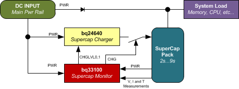
bq33100 系统图
