ZHCS952C June 2012 – January 2015 UCD8220-Q1
PRODUCTION DATA.
- 1 特性
- 2 应用
- 3 说明
- 4 修订历史记录
- 5 Pin Configuration and Functions
- 6 Specifications
- 7 Detailed Description
- 8 Application and Implementation
- 9 Power Supply Recommendations
- 10Layout
- 11器件和文档支持
- 12机械、封装和可订购信息
1 特性
- 具有符合 AEC-Q100 的下列结果:器件从预览变为生产
- 器件温度 1 级:-40°C 至 125°C 的环境运行温度范围
- 器件人体模型 (HBM) 静电放电 (ESD) 分类等级 2
- 器件组件充电模式 (CDM) ESD 分类等级 C4B
- 用于使用 μC 或者 TMS320 ™数字信号处理器 (DSP) 系列的数控电源
- 带有逐周期电流限制的电压或者峰值电流模式控制
- 来自数字控制器的时钟输入设定运行频率和最大占空比
- 模拟 PWM 比较器
- 2MHz 开关频率
- 110V 输入启动电路和热关断 (UCD8620)
- 内部可编程斜率补偿
- 3.3V,10mA 线性稳压器
- DSP/μC 兼容输入
- 双 ±4A TrueDrive™集成电路高电流驱动器
- 由 2.2nF 电容实现的 10ns 典型上升和下降时间
- 25ns 输入到输出传播延迟
- 25ns 电流感测到输出传播延迟
- 可编程电流限制阈值
- 数字输出电流限制标志
- 4.5V 至 15.5V 电源电压范围
2 应用
- 混合动力汽车/电动汽车 (HEV/EV) 和动力总成
- 数控开关模式电源
- 推挽、半桥、或全桥转换器
- 电池充电器
3 说明
UCD8220-Q1 模拟脉宽调制器 (PWM) 器件适用于采用微控制器或者 TMS320 DSP 系列的数控电源。
UCS8220-Q1 器件是一款配有推挽驱动逻辑的双端 PWM 控制器。
使用 UCD8220-Q1 的系统使用传统模拟方法闭合 PWM 反馈环路,但是 UCD8220-Q1 控制器也包括用于解释一个时域数字连续脉冲信号的电路。这个连续脉冲信号包含用于控制电源操作的运行频率和最大占空比限制。该器件的电路简化了具有高电平控制 特性 的转换器的实现方式,无需在离散时域中闭合控制环路,因而不会造成额外的复杂性或可能的 PWM 分辨率限制。
UCD8220-Q1 器件可配置为峰值电流模式或电压模式控制。此器件提供了可编程电流限制功能和一个可由主机控制器加以监控的数字输出电流限制标志,用于设定限流操作。为了实现快速开关速度,输出级采用 TrueDrive 输出电路架构,此架构传送 ±4A 的额定电流进入 MOSFET 的栅极。最后,该器件还包括一个 3.3V、10mA 的线性稳压器,该稳压器能够为数字控制器供电或用作系统中的一个基准。
UCD8220-Q1 控制器与 UCD9K 数字电源控制器,DSP,微控制器,或者 ASIC 的 3.3V 标准 I/O 端口兼容并封装在 PowerPAD™集成电路散热薄型小尺寸封装 (HTSSOP) 内。
器件信息(1)
| 器件型号 | 封装 | 封装尺寸(标称值) |
|---|---|---|
| UCD8220-Q1 | HTSSOP (16) | 5.00mm x 4.40mm |
- 如需了解所有可用封装,请见数据表末尾的可订购产品附录。
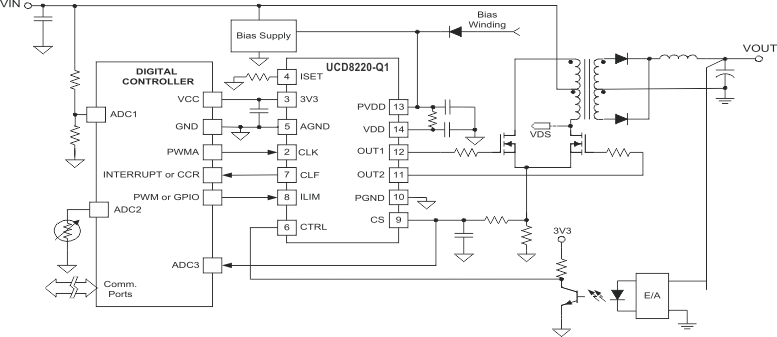
UCD8220-Q1 典型简化推挽转换器应用电路原理图

4 修订历史记录
Changes from B Revision (July 2014) to C Revision
- Added 向数据表中添加了以下部分:器件功能模式、应用信息、设计要求、应用曲线、电源建议 和布局示例Go
- Changed the Handling Ratings table to ESD ratings and moved the storage temperature into the Absolute Maximum Ratings table Go
Changes from A Revision (June 2012) to B Revision
- 更新了数据表格式以满足新的 TI 数据表标准Go
- Deleted VIN (input to internal start-up circuitry) from the Pin Functions table Go
- Added the Clearing the Current-Limit Flag (CLF) sectionGo
Changes from * Revision (June 2012) to A Revision