TIDUEA0A March 2019 – September 2020
- Description
- Resources
- Features
- Applications
- 5
- 1System Description
- 2System Overview
-
3Hardware, Software, Testing Requirements, and Test Results
- 3.1 Required Hardware and Software
- 3.2
Testing and Results
- 3.2.1 Test Setup for Performance Testing
- 3.2.2 EMI and EMC Test Requirements for DRTD
- 3.2.3 TMP117 EMI/EMC Test Results
- 3.2.4 TMP117 Based Temperature Probe Measurement Performance Test Results
- 3.2.5 TMP116 Based Temperature Probe Measurement Performance Test Results
- 3.2.6 I2C-bus Cable Length Considerations
- 3.2.7 Power Supply
- 3.2.8 ESD Test Results for TMP116
- 3.2.9 Summary
- 4Design Files
- 5Software Files
- 6Related Documentation
- 7About the Author
- 8Revision History
2.1 Block Diagram
Heat and Cooling Meters are becoming more and more popular in EMEA, Russia, and China markets, as the requirements for billing thermal energy (heat and cold) are steadily increasing. As the measurement cycle of these devices is configurable and is typically less frequent than once in a few seconds, the complete DTM subsystem is powered-off between the measurements. Such an approach is highly beneficial not only in all battery-powered products but also for any application with limited available power, such as M-Bus wired or 4- to 20-mA industrial sensors.
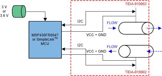
The TIDA-010002 can be placed into the standard 5.2-mm diameter metal sheath for RTDs as used in Heat Meters, and assembled with a 4-wire cable as a DRTD sensor. The DRTD is then immersed into the inlet and outlet flow, as shown in red in Figure 2-1.
 Figure 2-1 TIDA-010002 Block Diagram