TIDUEA0A March 2019 – September 2020
- Description
- Resources
- Features
- Applications
- 5
- 1System Description
- 2System Overview
-
3Hardware, Software, Testing Requirements, and Test Results
- 3.1 Required Hardware and Software
- 3.2
Testing and Results
- 3.2.1 Test Setup for Performance Testing
- 3.2.2 EMI and EMC Test Requirements for DRTD
- 3.2.3 TMP117 EMI/EMC Test Results
- 3.2.4 TMP117 Based Temperature Probe Measurement Performance Test Results
- 3.2.5 TMP116 Based Temperature Probe Measurement Performance Test Results
- 3.2.6 I2C-bus Cable Length Considerations
- 3.2.7 Power Supply
- 3.2.8 ESD Test Results for TMP116
- 3.2.9 Summary
- 4Design Files
- 5Software Files
- 6Related Documentation
- 7About the Author
- 8Revision History
2.4.3 Digital RTD Solution Using TMP117
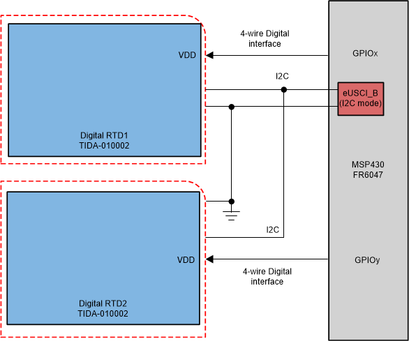
The TIDA-010002 integrates the entire DTM subsystem into a single device by combining the Delta-Sigma core and the RTD into a highly accurate digital temperature sensor (see Figure 2-7). Note that the 4-wire digital interface of the TIDA-010002 is not electrically compatible to the standard analog 4-wire RTD sensor, measured with the help of the Kelvin connection as Figure 2-5 shows.
 Figure 2-7 Integration of the Analog Measurement Chain Into a Semiconductor Temperature Sensors TMP117 With Digital I2C Interface
The 4-wire digital interface requires the supply voltage VDD, which can be provided by a GPIO pin of the host MCU, such as GPIOx in Figure 2-7. An additional GPIO pin, called GPIOy, can be used to power on and off the second DRTD sensor, and a 3rd GPIO and 4th pin can be added, in case more than two DRTD sensors have to be used. Using a dedicated GPIO pin to power each connected DRTD has the advantage, that all of those can be used on the same I2C-bus and still have the same I2C-address. The user has to ensure that only one GPIO pin of the host MCU is active (or HIGH), while all the others on the same I2C-bus lines having the same I2C address are inactive (or LOW).
As TMP117 integrates the complete temperature measurement subsystem using a thermal BJT and a 16-bit Delta-Sigma core into a fully digital solution, there is no extra temperature conversion effort to be done by the host MCU. The latter reads out the value and applies an offset (if needed), based on the parameters in the NV memory of the TMP117 device. It is more energy efficient to read out the NV memory content once at the beginning and apply the offset or any other adjustments to the result, each time the temperature is measured. The calibration offset data is stored into the NV memory as part of the DRTD manufacturing process or during end system calibration.
An important benefit of the DRTD approach, introduced here, is the elimination of offset and gain calibration steps for the analog signal chain, required with traditional analog signal measurements in 2-, 3-, or 4-wire configurations.
The high precision Reference resistor, typically with accuracy better than 0.1% and ±25 ppm/C, and the matched RC-filters are not needed anymore. This represents a cost reduction in terms of Bill of materials as well as in PCB space and a much simplified layout on the host MCU side.
Last but not least, for all Heat and Cooling meters with precision temperature measurement in the –55°C to 150°C range, TIDA-010002 is expected to enable significantly lower cost in manufacturing by reducing the three temperature points calibration as in EN 1434 to a single point temperature offset calibration.
A major advantage of the DRTD approach, based upon the TIDA-010002, is the capability to store user defined calibration parameters in the EEPROM memory area of the TMP117 device. This significantly simplifies and can even completely eliminate the paperwork and calibration data handling efforts when compared to traditional analog RTD sensors. In the case of the latter, labels with an ID number have to be attached to the RTD cable. The calibration data is then passed over to the Meter vendor by the RTD sensor vendor by some off-line means, for example, in an electronic data format.
A 1-point offset calibration at 0°C or at room temperature may be required to achieve Class AA accuracy; this calibration step will narrow the 3-sigma accuracy spread of the TMP117 device down to the average curve shown on TMP117 High-Accuracy, Low-Power, Digital Temperature Sensor With SMBus- and I2C-Compatible Interface.