SPRACR2 March 2020 TMS320F280021 , TMS320F280021-Q1 , TMS320F280023 , TMS320F280023-Q1 , TMS320F280023C , TMS320F280025 , TMS320F280025-Q1 , TMS320F280025C , TMS320F280025C-Q1
- Enabling Peripheral Expansion Applications Using the HIC
- A Address Translation for Different Data Width Modes
2.5.2 Software Interrupts
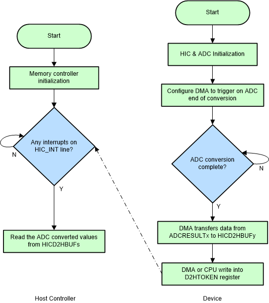
The HIC provides a software method to generate an interrupt to the Host. Any write into the HICD2HTOKEN register will trigger an interrupt on the HIC_INT pin. This method enables the extension of Host interrupt capability to Device peripherals that do not have direct interrupts mapped to the EVTRIG bus. For example, Figure 9 shows the Host-Device sequence to interrupt the Host CPU on a Device ADC End Of Conversion event.
Custom data exchange protocols can be implemented using the mailbox registers (D2H_BUFn and H2D_BUFn) and the token registers. For example, the Device can fill the D2H_BUFn registers with data to be exchanged and notify the Host by writing HICD2HTOKEN register with the number of words available in the D2H_BUFn registers.
 Figure 9. Software Interrupt Usage Model