SPRACR2 March 2020 TMS320F280021 , TMS320F280021-Q1 , TMS320F280023 , TMS320F280023-Q1 , TMS320F280023C , TMS320F280025 , TMS320F280025-Q1 , TMS320F280025C , TMS320F280025C-Q1
- Enabling Peripheral Expansion Applications Using the HIC
- A Address Translation for Different Data Width Modes
2.4 Read/write I/O Configuration
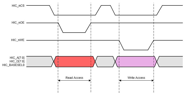
The HIC supports dual pin and single pin mode for read and write configuration which is controlled by the HICMODECR.RnW register field. In case of dual pin mode, the HIC_nCS acts as the enable pin, whereas, the HIC_nOE for reads and HIC_nWE for writes acts as the strobe/select for each access. Figure 6 shows the timing diagram of the read and write access in dual pin mode.
 Figure 6. Read and Write Access in Dual Pin Mode
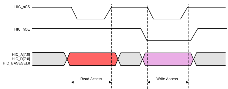
 In the single pin mode, the HIC_nCS pin acts as the strobe/select for each access and the HIC_nOE pin acts as a level pin to select read or write. It indicates a read acess when set to 1 and a write access when set to 0. Figure 7 shows the timing diagram of the read and write access in single pin mode.
 Figure 7. Read and Write Access in Single Pin Mode
 If the Host memory controller supports strobe timing control of HIC_nCS for each access, the application can take advantage of the single pin mode and free up one pin for other requirements. One example of this mode is the select strobe mode supported by the C2000 External Memory Interface (EMIF) controller.