ZHCSGF3B July   2017  – January 2019 TPS7A92

PRODUCTION DATA.  

  1. 特性
  2. 应用
  3. 说明
    1.     Device Images
      1.      典型应用电路
      2.      典型应用图
  4. 修订历史记录
  5. Pin Configuration and Functions
    1.     Pin Functions
  6. Specifications
    1. 6.1 Absolute Maximum Ratings
    2. 6.2 ESD Ratings
    3. 6.3 Recommended Operating Conditions
    4. 6.4 Thermal Information
    5. 6.5 Electrical Characteristics
    6. 6.6 Typical Characteristics
  7. Detailed Description
    1. 7.1 Overview
    2. 7.2 Functional Block Diagram
    3. 7.3 Feature Description
      1. 7.3.1 Output Enable
      2. 7.3.2 Dropout Voltage (VDO)
      3. 7.3.3 Output Voltage Accuracy
      4. 7.3.4 High Power-Supply Ripple Rejection (PSRR)
      5. 7.3.5 Low Output Noise
      6. 7.3.6 Output Soft-Start Control
      7. 7.3.7 Power-Good Function
      8. 7.3.8 Internal Protection Circuitry
        1. 7.3.8.1 Undervoltage Lockout (UVLO)
        2. 7.3.8.2 Internal Current Limit (ICL)
        3. 7.3.8.3 Thermal Protection
    4. 7.4 Device Functional Modes
      1. 7.4.1 Normal Operation
      2. 7.4.2 Dropout Operation
      3. 7.4.3 Disabled
  8. Application and Implementation
    1. 8.1 Application Information
      1. 8.1.1 Adjustable Output
      2. 8.1.2 Start-Up
        1. 8.1.2.1 Enable (EN) and Undervoltage Lockout (UVLO)
        2. 8.1.2.2 Noise-Reduction and Soft-Start Capacitor (CNR/SS)
          1. 8.1.2.2.1 Noise Reduction
          2. 8.1.2.2.2 Soft-Start and Inrush Current
      3. 8.1.3 Capacitor Recommendation
        1. 8.1.3.1 Input and Output Capacitor Requirements (CIN and COUT)
          1. 8.1.3.1.1 Load-Step Transient Response
        2. 8.1.3.2 Feed-Forward Capacitor (CFF)
      4. 8.1.4 Power Dissipation (PD)
      5. 8.1.5 Estimating Junction Temperature
    2. 8.2 Typical Application
      1. 8.2.1 Design Requirements
      2. 8.2.2 Detailed Design Procedure
      3. 8.2.3 Application Curves
  9. Power Supply Recommendations
  10. 10Layout
    1. 10.1 Layout Guidelines
      1. 10.1.1 Board Layout
    2. 10.2 Layout Example
  11. 11器件和文档支持
    1. 11.1 器件支持
      1. 11.1.1 开发支持
        1. 11.1.1.1 评估模块
        2. 11.1.1.2 Spice 模型
      2. 11.1.2 器件命名规则
    2. 11.2 文档支持
      1. 11.2.1 相关文档
    3. 11.3 接收文档更新通知
    4. 11.4 社区资源
    5. 11.5 商标
    6. 11.6 静电放电警告
    7. 11.7 术语表
  12. 12机械、封装和可订购信息

封装选项

机械数据 (封装 | 引脚)
散热焊盘机械数据 (封装 | 引脚)
订购信息

Output Soft-Start Control

Soft-start refers to the ramp-up characteristic of the output voltage during LDO turn-on after the EN and UVLO thresholds are exceeded. The noise-reduction capacitor (CNR/SS) serves a dual purpose of both governing output noise reduction and programming the soft-start ramp during turn-on. Larger values for the noise-reduction capacitors decrease the noise but also result in a slower output turn-on ramp rate.

The TPS7A92 features an SS_CTRL pin. When the SS_CTRL pin is grounded, the charging current for the NR/SS pin is 6.2 µA (typ); when this pin is connected to IN, the charging current for the NR/SS pin is increased to 100 µA (typ).  The higher current allows the use of a much larger noise-reduction capacitor and maintains a reasonable startup time. Figure 36 shows a simplified block diagram of the soft-start circuit. The switch SW is opened to turn off the INR/SS current source after VFB reaches approximately 97% of VREF. The final 3% of VNR/SS is charged through the noise reduction resistor (RNR), which creates an RC delay. RNR is approximately 280 kΩ and applications that require the highest accuracy when using a large value CNR/SS must take this RC delay into account.

If a noise-reduction capacitor is not used on the NR/SS pin, tying the SS_CTRL pin to the IN pin can result in output voltage overshoot of approximately 10%. This overshoot is minimized by either connecting the SS_CTRL pin to GND or using a capacitor on the NR/SS pin.
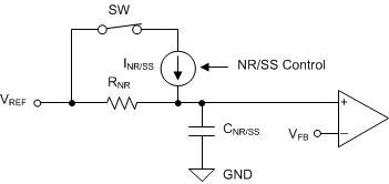
TPS7A92 ai_softstart_sbvs282.gifFigure 36. Simplified Soft-Start Circuit