ZHCSFZ1A January   2017  – July 2018 DRV8886

UNLESS OTHERWISE NOTED, this document contains PRODUCTION DATA.  

  1. 特性
  2. 应用
  3. 说明
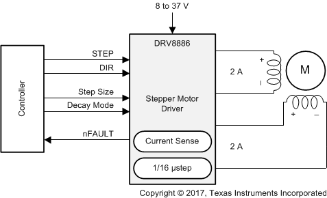
    1.     简化原理图
  4. 修订历史记录
  5. Pin Configuration and Functions
    1.     Pin Functions
  6. Specifications
    1. 6.1 Absolute Maximum Ratings
    2. 6.2 ESD Ratings
    3. 6.3 Recommended Operating Conditions
    4. 6.4 Thermal Information
    5. 6.5 Electrical Characteristics
    6. 6.6 Indexer Timing Requirements
    7. 6.7 Typical Characteristics
  7. Detailed Description
    1. 7.1 Overview
    2. 7.2 Functional Block Diagram
    3. 7.3 Feature Description
      1. 7.3.1  Stepper Motor Driver Current Ratings
        1. 7.3.1.1 Peak Current Rating
        2. 7.3.1.2 rms Current Rating
        3. 7.3.1.3 Full-Scale Current Rating
      2. 7.3.2  PWM Motor Drivers
      3. 7.3.3  Microstepping Indexer
      4. 7.3.4  Current Regulation
      5. 7.3.5  Controlling RREF With an MCU DAC
      6. 7.3.6  Decay Modes
        1. 7.3.6.1 Mode 1: Slow Decay for Increasing Current, Mixed Decay for Decreasing Current
        2. 7.3.6.2 Mode 2: Mixed Decay for Increasing and Decreasing Current
        3. 7.3.6.3 Mode 3: Slow Decay for Increasing and Decreasing Current
      7. 7.3.7  Blanking Time
      8. 7.3.8  Charge Pump
      9. 7.3.9  Linear Voltage Regulators
      10. 7.3.10 Logic and Multi-Level Pin Diagrams
      11. 7.3.11 Protection Circuits
        1. 7.3.11.1 VM Undervoltage Lockout (UVLO)
        2. 7.3.11.2 VCP Undervoltage Lockout (CPUV)
        3. 7.3.11.3 Overcurrent Protection (OCP)
        4. 7.3.11.4 Thermal Shutdown (TSD)
    4. 7.4 Device Functional Modes
  8. Application and Implementation
    1. 8.1 Application Information
    2. 8.2 Typical Application
      1. 8.2.1 Design Requirements
      2. 8.2.2 Detailed Design Procedure
        1. 8.2.2.1 Stepper Motor Speed
        2. 8.2.2.2 Current Regulation
        3. 8.2.2.3 Decay Modes
      3. 8.2.3 Application Curves
  9. Power Supply Recommendations
    1. 9.1 Bulk Capacitance
  10. 10Layout
    1. 10.1 Layout Guidelines
    2. 10.2 Layout Example
  11. 11器件和文档支持
    1. 11.1 文档支持
      1. 11.1.1 相关文档
    2. 11.2 接收文档更新通知
    3. 11.3 社区资源
    4. 11.4 商标
    5. 11.5 静电放电警告
    6. 11.6 术语表
  12. 12机械、封装和可订购信息

封装选项

机械数据 (封装 | 引脚)
散热焊盘机械数据 (封装 | 引脚)
订购信息

说明

DRV8886 是一款适用于工业和消费类终端设备的 步进电机驱动器。该器件与两个 N 沟道功率金属氧化物半导体场效应晶体管 (MOSFET) H 桥驱动器、一个微步进分度器以及集成电流检测功能完全集成。DRV8886 能够驱动高达 2A 的满量程电流或 1.4A rms 输出电流(电压为 24V 且 TA = 25°C,取决于印刷电路板 (PCB) 设计)。

DRV8886 采用内部电流检测架构,无需使用两个外部功率感测电阻,从而缩小 PCB 面积并削减系统成本。DRV8886 使用内部固定关断时间 PWM 电流调节方案,可在慢速和混合衰减选项之间进行调节。

简易 STEP/DIR 接口允许外部控制器管理步进电机的方向和步进速率。该器件可以配置为不同步进模式,范围涵盖整步至 1/16 微步。凭借专用 nSLEEP 引脚,该器件可提供一种低功耗休眠模式,从而实现超低静态待机电流。

该器件的 保护功能 包括:电源欠压、电荷泵故障、过流、短路以及过热保护。故障状态通过 nFAULT 引脚指示。

器件信息 (1)

器件型号 封装 封装尺寸(标称值)
DRV8886 HTSSOP (24) 7.80mm × 4.40mm
WQFN(2) (28) 5.50mm × 3.5mm
  1. 如需了解所有可用封装,请参阅数据表末尾的可订购产品附录。
  2. 仅供预览。

简化原理图

DRV8886 fbd_FAD_DRV8886.gif