ZHCSC08C December 2013 – August 2015 DLPC6401
PRODUCTION DATA.
- 1 特性
- 2 应用
- 3 说明
- 4 修订历史记录
- 5 Pin Configuration and Functions
-
6 Specifications
- 6.1 Absolute Maximum Ratings
- 6.2 ESD Ratings
- 6.3 Recommended Operating Conditions
- 6.4 Thermal Information
- 6.5 Electrical Characteristics
- 6.6 Electrical Characteristics (Normal Mode)
- 6.7 System Oscillators Timing Requirements
- 6.8 Test and Reset Timing Requirements
- 6.9 JTAG Interface: I/O Boundary Scan Application Timing Requirements
- 6.10 Port 1 Input Pixel Interface Timing Requirements
- 6.11 Port 2 Input Pixel Interface (FPD-Link Compatible LVDS Input) Timing Requirements
- 6.12 Synchronous Serial Port (SSP) Interface Timing Requirements
- 6.13 Programmable Output Clocks Switching Characteristics
- 6.14 Synchronous Serial Port (SSP) Interface Switching Characteristics
- 6.15 JTAG Interface: I/O Boundary Scan Application Switching Characteristics
- 7 Detailed Description
- 8 Application and Implementation
- 9 Power Supply Recommendations
- 10Layout
- 11器件和文档支持
- 12机械、封装和可订购信息
11 器件和文档支持
11.1 器件支持
11.1.1 器件命名规则
11.1.1.1 视频时序参数定义
-
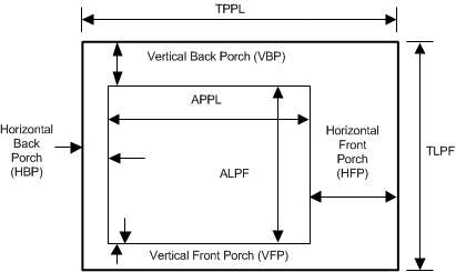
每帧有效扫描行数 (ALPF) 定义一帧中包含可显示数据的行数:ALPF 是每帧总行数 (TLPF) 的子集。
-
每行有效像素 (APPL) 定义包含可显示数据的一行中的像素时钟数:APPL 是每行总像素 (TPPL) 的子集。
-
水平后沿 (HBP) 消隐 水平同步之后,第一个有效像素之前的消隐像素时钟数量。注意:HBP 时间以各自同步信号的前缘(有效)边沿为基准。
-
水平前沿 (HFP) 消隐 最后一个有效时钟之后,水平同步之前的消隐像素时钟的数量。
-
水平同步 (HS) 定义水平间隔(行)开始的时序基准点。绝对基准点由 HS 信号的有效边沿定义。有效边沿(源定义的上升沿或下降沿)是测量所有水平消隐参数的基准。
-
每帧总行数 (TLPF) 以行数定义垂直扫描时间(帧时间):TLPF = 每帧总行数(有效和无效行)
-
每行总像素 (TPPL) 以像素时钟数定义水平行扫描时间:TPPL = 每行总像素时钟数(有效和无效像素时钟)
-
垂直后沿 (VBP) 消隐 垂直同步后,第一个有效行之前的消隐行的数量。
-
垂直前沿 (VFP) 消隐 最后有效行之后,垂直同步前的消隐行的数量。
-
垂直同步 (VS) 定义垂直间隔(帧)开始的时序基准点。这个绝对基准点由 VS 信号的有效边沿定义。有效边沿(源定义的上升沿或下降沿)是测量所有垂直消隐参数的基准。
 Figure 22. 时序参数图
11.2 社区资源
The following links connect to TI community resources. Linked contents are provided "AS IS" by the respective contributors. They do not constitute TI specifications and do not necessarily reflect TI's views; see TI's Terms of Use.
-
TI E2E™ Online Community TI's Engineer-to-Engineer (E2E) Community. Created to foster collaboration among engineers. At e2e.ti.com, you can ask questions, share knowledge, explore ideas and help solve problems with fellow engineers.
-
Design Support TI's Design Support Quickly find helpful E2E forums along with design support tools and contact information for technical support.
11.3 商标
E2E is a trademark of Texas Instruments.
DLP is a registered trademark of Texas Instruments.
ARM926 is a trademark of ARM.
All other trademarks are the property of their respective owners.
11.4 静电放电警告

这些装置包含有限的内置 ESD 保护。 存储或装卸时,应将导线一起截短或将装置放置于导电泡棉中,以防止 MOS 门极遭受静电损伤。
11.5 Glossary
SLYZ022 — TI Glossary.
This glossary lists and explains terms, acronyms, and definitions.
