ZHCSRG2G May 2001 – December 2022 BQ2057C
PRODUCTION DATA
- 1 特性
- 2 应用
- 3 说明
- 4 Revision History
- 5 说明(续)
- 6 Device Comparison Table
- 7 Pin Configuration and Functions
- 8 Specifications
- 9 Detailed Description
-
10Application and Implementation
- 10.1
Application Information
- 10.1.1 Functional Description
- 10.1.2 Qualification and Precharge
- 10.1.3 Current Regulation Phase
- 10.1.4 Voltage Regulation Phase
- 10.1.5 Charge Termination and Recharge
- 10.1.6 Battery Temperature Monitoring
- 10.1.7 Charge Inhibit Function
- 10.1.8 Charge Status Indication
- 10.1.9 Low-power Sleep Mode
- 10.1.10 Selecting an External Pass-Transistor
- 10.1.11 Selecting Input Capacitor
- 10.1.12 Selecting Output Capacitor
- 10.1.13 Automatic Charge-rate Compensation
- 10.2 Typical Application
- 10.1
Application Information
- 11Power Supply Recommendations
- 12Layout
- 13Device and Documentation Support
- 14Mechanical, Packaging, and Orderable Information
封装选项
请参考 PDF 数据表获取器件具体的封装图。
机械数据 (封装 | 引脚)
- D|8
- DGK|8
- PW|8
散热焊盘机械数据 (封装 | 引脚)
订购信息
10.1.8 Charge Status Indication
The BQ2057 reports the status of the charger on the 3-state STAT pin. The following table summarized the operation of the STAT pin.
| CONDITION | STAT PIN |
|---|---|
| Battery conditioning and charging | High |
| Charge complete (Done) | Low |
| Temperature fault or sleep mode | Hi-Z |
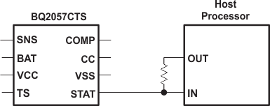
The STAT pin can be used to drive a single LED (Figure 10-1), dual-chip LEDs (Figure 4) or for interface to a host or system processor (Figure 10-11). When interfacing the BQ2057 to a processor, the user can use an output port, as shown in Figure 10-11, to recognize the Hi-Z state of the STAT pin. In this configuration, the user needs to read the input pin, toggle the output port and read the STAT pin again. In a Hi-Z condition, the input port always matches the signal level on the output port.
 Figure 10-11 Interfacing the BQ2057 to a Host Processor