产品详情

Technology family CD4000 Bits (#) 1 Rating Catalog Operating temperature range (°C) -55 to 125
PDIP (N) 14 181.42 mm² (19.3 mm × 9.4 mm) TSSOP (PW) 14 32 mm² (5 mm × 6.4 mm) SOIC (D) 14 51.9 mm² (8.65 mm × 6 mm) SOP (NS) 14 79.56 mm² (10.2 mm × 7.8 mm)
  • Low Symmetrical Output Resistance, Typically 100 at VDD = 15V
  • Built-In Low-Power RC Oscillator
  • Oscillator Frequency Range . . . DC to 100kHz
  • External Clock (Applied to Pin 3) can be Used Instead of Oscillator
  • Operates as 2 N Frequency Divider or as a Single-Transition Timer
  • Q/Q\ Select Provides Output Logic Level Flexibility
  • AUTO or MASTER RESET Disables Oscillator During Reset to Reduce Power Dissipation
  • Operates With Very Slow Clock Rise and Fall Times
  • Capable of Driving Six Low Power TTL Loads, Three Low-Power Schottky Loads, or Six HTL Loads Over the Rated Temperature Range
  • Symmetrical Output Characteristics
  • 100% Tested for Quiescent Current at 20V
  • 5V, 10V, and 15V Parametric Ratings
  • Meets All Requirements of JEDEC Standard No. 13B, "Standard Specifications for Description of ’B’ Series CMOS Devices"

Data sheet acquired from Harris Semiconductor

  • Low Symmetrical Output Resistance, Typically 100 at VDD = 15V
  • Built-In Low-Power RC Oscillator
  • Oscillator Frequency Range . . . DC to 100kHz
  • External Clock (Applied to Pin 3) can be Used Instead of Oscillator
  • Operates as 2 N Frequency Divider or as a Single-Transition Timer
  • Q/Q\ Select Provides Output Logic Level Flexibility
  • AUTO or MASTER RESET Disables Oscillator During Reset to Reduce Power Dissipation
  • Operates With Very Slow Clock Rise and Fall Times
  • Capable of Driving Six Low Power TTL Loads, Three Low-Power Schottky Loads, or Six HTL Loads Over the Rated Temperature Range
  • Symmetrical Output Characteristics
  • 100% Tested for Quiescent Current at 20V
  • 5V, 10V, and 15V Parametric Ratings
  • Meets All Requirements of JEDEC Standard No. 13B, "Standard Specifications for Description of ’B’ Series CMOS Devices"

Data sheet acquired from Harris Semiconductor

CD4541B programmable timer consists of a 16-stage binary counter, an oscillator that is controlled by external R-C components (2 resistors and a capacitor), an automatic power-on reset circuit, and output control logic. The counter increments on positive-edge clock transitions and can also be reset via the MASTER RESET input.

The output from this timer is the Q or Q\ output from the 8th, 10th, 13th, or 16th counter stage. The desired stage is chosen using time-select inputs A and B (see Frequency Select Table).

The output is available in either of two modes selectable via the MODE input, pin 10 (see Truth Table). When this MODE input is a logic "1", the output will be a continuous square wave having a frequency equal to the oscillator frequency divided by 2N. With the MODE input set to logic "0" and after a MASTER RESET is initiated, the output (assuming Q output has been selected) changes from a low to a high state after 2N-1 counts and remains in that state until another MASTER RESET pulse is applied or the MODE input is set to a logic "1".

Timing is initialized by setting the AUTO RESET input (pin 5) to logic "0" and turning power on. If pin 5 is set to logic "1", the AUTO RESET circuit is disabled and counting will not start until after a positive MASTER RESET pulse is applied and returns to a low level. The AUTO RESET consumes an appreciable amount of power and should not be used if low-power operation is desired. For reliable automatic power-on reset, VDD should be greater than 5V.

The RC oscillator, shown in Figure 2, oscillates with a frequency determined by the RC network and is calculated using:
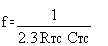
Where f is between 1kHz and 100kHz and RS and 2RTC.

CD4541B programmable timer consists of a 16-stage binary counter, an oscillator that is controlled by external R-C components (2 resistors and a capacitor), an automatic power-on reset circuit, and output control logic. The counter increments on positive-edge clock transitions and can also be reset via the MASTER RESET input.

The output from this timer is the Q or Q\ output from the 8th, 10th, 13th, or 16th counter stage. The desired stage is chosen using time-select inputs A and B (see Frequency Select Table).

The output is available in either of two modes selectable via the MODE input, pin 10 (see Truth Table). When this MODE input is a logic "1", the output will be a continuous square wave having a frequency equal to the oscillator frequency divided by 2N. With the MODE input set to logic "0" and after a MASTER RESET is initiated, the output (assuming Q output has been selected) changes from a low to a high state after 2N-1 counts and remains in that state until another MASTER RESET pulse is applied or the MODE input is set to a logic "1".

Timing is initialized by setting the AUTO RESET input (pin 5) to logic "0" and turning power on. If pin 5 is set to logic "1", the AUTO RESET circuit is disabled and counting will not start until after a positive MASTER RESET pulse is applied and returns to a low level. The AUTO RESET consumes an appreciable amount of power and should not be used if low-power operation is desired. For reliable automatic power-on reset, VDD should be greater than 5V.

The RC oscillator, shown in Figure 2, oscillates with a frequency determined by the RC network and is calculated using:

Where f is between 1kHz and 100kHz and RS and 2RTC.

下载 观看带字幕的视频 视频

您可能感兴趣的相似产品

open-in-new 比较替代产品
功能与比较器件相似。
TPL5010 正在供货 具有看门狗功能和手动复位功能的毫微功耗系统计时器 Watchdog timer

技术文档

未找到结果。请清除搜索并重试。
查看全部 1
顶层文档 类型 标题 格式选项 下载最新的英语版本 日期
* 数据表 CD4541B 数据表 (Rev. E) 2003-8-21

设计与开发

如需其他信息或资源,请点击以下任一标题进入详情页面查看(如有)。

评估板

14-24-LOGIC-EVM — 采用 14 引脚至 24 引脚 D、DB、DGV、DW、DYY、NS 和 PW 封装的逻辑产品通用评估模块

14-24-LOGIC-EVM 评估模块 (EVM) 设计用于支持采用 14 引脚至 24 引脚 D、DW、DB、NS、PW、DYY 或 DGV 封装的任何逻辑器件。

用户指南: PDF | HTML
支持的产品和硬件
有库存
限制:
??asset.out-of-stock-ti_zh_CN??
无货
封装 引脚 CAD 符号、封装和 3D 模型
PDIP (N) 14 Ultra Librarian
TSSOP (PW) 14 Ultra Librarian
SOIC (D) 14 Ultra Librarian
SOP (NS) 14 Ultra Librarian

订购和质量

支持和培训

可获得 TI 工程师技术支持的 TI E2E™ 论坛

所有内容均由 TI 和社区贡献者按“原样”提供,并不构成 TI 规范。请参阅使用条款

如果您对质量、包装或订购 TI 产品有疑问,请参阅 TI 支持。​​​​​​​​​​​​​​

视频