SLLA528 September 2020 – MONTH DRV8106-Q1 , DRV8706-Q1 , DRV8714-Q1 , DRV8718-Q1
Tech Note
Abstract
When driving brushed DC motors, the ability to measure and monitor current is advantageous for several reasons, and there are a variety of methods for doing this with varying tradeoffs. This application note will focus on how a wide common mode differential current shunt amplifier can be used for high-side current sensing and inline current sensing, and the advantages versus the traditional low-side current sensing techniques. Brushed DC motor driver devices like the DRV8706-Q1, DRV8714-Q1, and DRV8718-Q1 all implement a wide common mode current shunt amplifier with unique features like programmable gain, unidirectional and bidirectional support, output blanking and sample and hold switch, and dedicated voltage reference pin for setting a mid-point bias voltage for the amplifier output. Benefits include the ability to detect faults such as soft shorts in the motor system, continuous monitoring of current during recirculation periods, and implementing ripple counting techniques.
Introduction
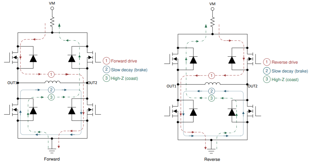
First, it is important to understand how motor current flows in a traditional DC motor system, and analyze the current flow assuming a traditional low-side current shunt resistor. When using an H-bridge to control current in the motor, typically a PWM technique is used to enable and disable output FETs in the drive stage. These different modes are shown in Figure 1 below. For the two drive states (1), forward and reverse, the current flows through one of the high-side FETs and one of the low-side FETs before finally passing through the low-side shunt resistor. A simple, single-ended low common mode range amplifier can be used to continuously monitor the current for the drive states. However, consider the case when current is recirculating during the brake state (2). In this case, the low-side current sense amplifier is “blind” to the recirculation current, as no current is passing through the shunt resistor. Or, consider the case when current is recirculating during the coast state (3) and current is passing in the opposite direction of drive states through the low-side shunt resistor. Measuring this current will require a bi-directional amplifier implementation on the low-side shunt.
 Figure 1-1 H-bridge States with Low-side
Shunt
Figure 1-1 H-bridge States with Low-side
ShuntHigh-Side Current Shunt Monitoring
Now consider the case with the current shunt resistor is implemented between the power supply, VM, and drain of the high-side transistors as shown in Figure 2 below. For each of the drive states (1), current will flow from the supply through the current shunt resistor and down through the transistors to ground. A high common mode range amplifier will be necessary to accommodate the power supply voltage, but the input range would not need to be large as the voltage drop across the shunt resistor will only be several hundred millivolts. The amplifier will also need to be bi-directional if it is desired to monitor the current in the coast state (3). But, the same disadvantage of low-side current sensing remains during the brake state (2) for high-side sensing as well since the recirculating current never flows through the shunt resistor. There is one advantage of the high-side current shunt implementation and that is the ability to detect output-to-GND shorts. However, output-to-VM shorts would go undetected.
Inline Current Shunt Monitoring
Now consider the case when the current shunt resistor is implemented between one of the outputs and the load as shown in Figure 3 below. For each of the drive states (1), current will flow from the supply through the high-side transistor, current shunt resistor and down through the low-side to ground. A wide input, high common mode range amplifier will be necessary to accommodate the power supply voltage and near ground as the output is pulse width modulated (PWM). The amplifier will also need to be bi-directional to accommodate the forward and reverse states (1). But, the advantage versus previously discussed methods is the ability to continuously monitor current through the load during the brake state (2).
The only real disadvantage is fault monitoring as shorts directly on the outputs would go undetected as the current will bypass the shunt. For fault protection, the DRV87xx gate drivers incorporate a drain-to-source voltage (VDS) monitoring feature that protects against shorts to supply and ground. For more information on that, please read “Detecting Short to Battery & Ground Conditions with TI Motor Gate Drivers” (SLVAEV8).
 Figure 1-3 H-bridge States with Inline
Current Shunt
Figure 1-3 H-bridge States with Inline
Current ShuntChallenges of Inline Current Sensing
While the benefit is clear of inline current sensing with continuous current monitoring, it does not come without challenges. One of the biggest challenges is handling common-mode input swings from ground to supply as the output FETs switch during PWM. Please see Figure 4 below for a block diagram of the integrated amplifier in the DRV8706-Q1 device. Between the last amplifier stage and the output, an output blanking switch is implemented. This blanking circuit is synchronized to trigger on the active half-bridge and the blanking time is also adjustable. Please see Figure 5 for an illustration of the timing of this blanking and the resulting voltage on the amplifier output. This function is very beneficial to remove noise that occurs due to the wide common mode voltage swings present at the input to the amplifier. Additionally, the integrated amplifier allows for bidirectional current sensing with an adjustable bias voltage, AREF, applied to the output in the final stage of the amplifier.
 Figure 1-4 Detailed Block Diagram of
DRV8706-Q1 Amplifier
Figure 1-4 Detailed Block Diagram of
DRV8706-Q1 Amplifier Figure 1-5 Output Blanking during
PWM
Figure 1-5 Output Blanking during
PWMBenifits of Inline Current Sensing
The ability to monitor true phase current during the drive and brake states allows for motor position algorithms such as ripple counting. Ripple counting is a sensorless method for determining the relative position of a brushed DC motor in an application such as a memory seat or window in an automobile. As the motor rotates, the impedance seen by the BEMF periodically changes due to the nature of the DC motor brushes making contact with multiple poles of the motor and effectively shorting some of the motor windings. This change in impedance changes the measured current in a very periodic pattern proportional to the actual speed of the motor. By counting the “ripples” in the current waveform and knowing the poles of the motor, it is possible to know how many revolutions the motor has made between two points. This can be done without the aid of an external sensor like a magnetic sensor, or hall sensor. For more information on this technique, refer to “Automotive Brushed-Motor Ripple Counter Reference Design for Sensorless Position Measurement” (TIDA-01421).
Additionally, inline current sensing can be used to determine if there is a “soft” short in the system like a resistive short between motor leads and chassis due to insulation wear on the connecting wires. This type of soft short would be undetectable with traditional VDS monitors, but detectable with inline current sensing that is continuously monitoring the load current and able to detect small changes in current.
Finally, there is one other load configuration to be considered as all discussions so far have been around the H-bridge configuration. In the half-bridge configuration, an inline shunt resistor can be placed between the half-bridge output and the load which is commonly connected to ground. If there is a short on the motor terminal to GND, this will result in excessive current through the shunt resistor. If there is a short to the supply on the motor terminal, less than the expected current will flow through the shunt as current will be divided between the path with the direct short to supply and the path through the high-side transistor and shunt resistor.
Conclusion
In conclusion, there are several techniques for measuring current in a motor control system. Each has pros and cons, but the benefits of a wide input, high-common mode amplifier for high-side and inline current sensing are clear. The continuous current monitoring capability of the inline current sense allows for techniques such as ripple counting for sensorless position control. It also adds additional diagnostic capability in the system to detect small changes in the load current that could be the result of soft shorts in the motor wiring harness allowing for an early warning of a pending hard fault condition. Finally, the blanking feature in the DRV8706S-Q1, DRV8714S-Q1, and DRV8718S-Q1 solve the most difficult problem in measuring inline current by rejecting the noise that occurs due to the wide common mode voltage swings present at the input to the amplifier during PWM switching.