TIDT348 august 2023
2.4 Bode Plots
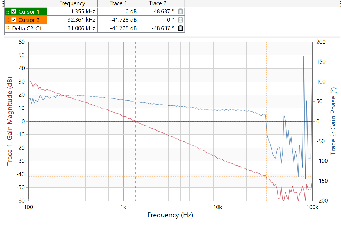
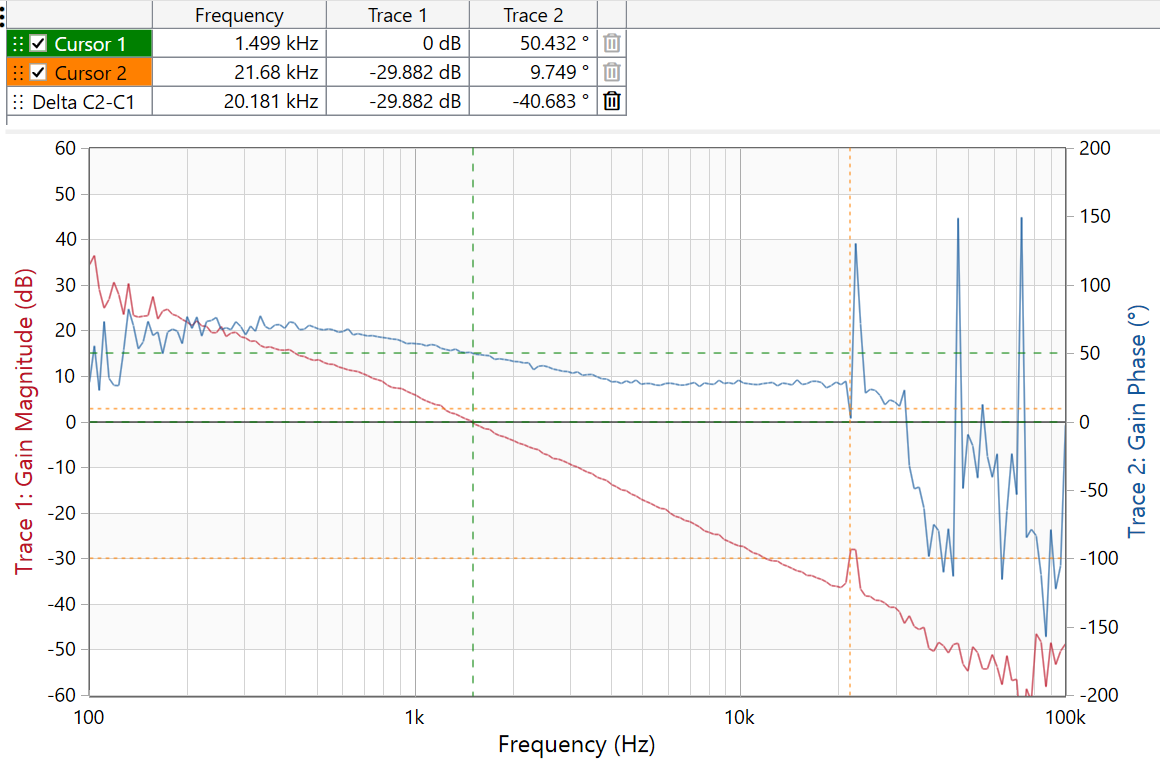
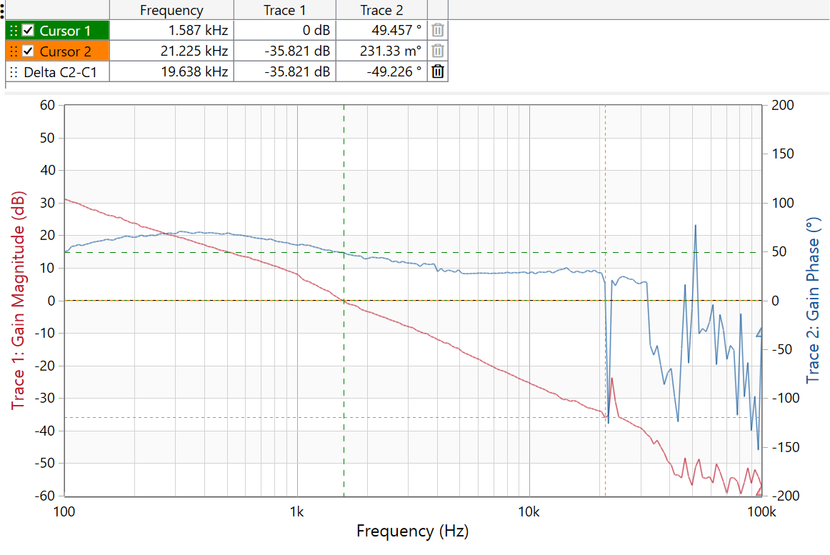
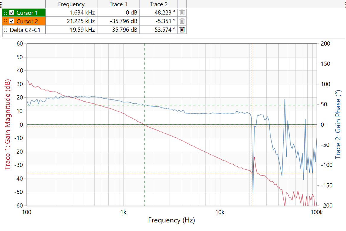
The following measurements show the loop response of the ZVS flyback at different AC input voltages and the 12-V output loaded to 1.5 A.
 Figure 2-7 90-Vac Input ZVS Flyback Loop
Measurement
 Figure 2-8 115-Vac Input ZVS Flyback Loop
Measurement
 Figure 2-9 230-Vac Input ZVS Flyback Loop
Measurement
 Figure 2-10 265-Vac Input ZVS Flyback Loop
Measurement