TIDT246 September 2021
4.3 Start-up
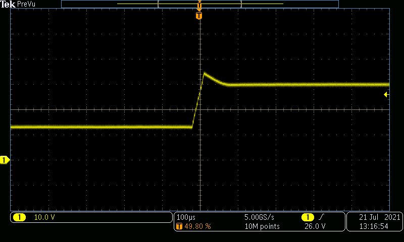
The start-up behavior of each converter is shown in the following figures. The boost converter start-up was measured on controller enable, the controller was disabled by shorting the COMP pin to GND. VOUT is shown in yellow.
 Figure 4-12 Boost Converter Start-up, 13.5
VIN, Maximum Load
Figure 4-12 Boost Converter Start-up, 13.5
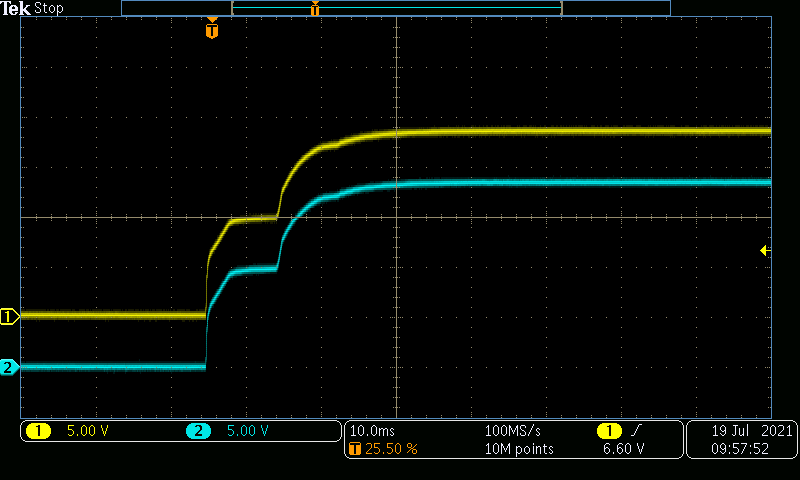
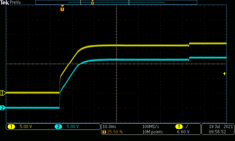
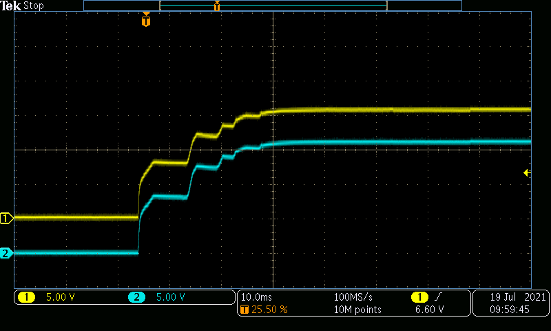
VIN, Maximum LoadFor the LLC converter, a 3-W output (yellow) and a 1-W output (blue) are shown.
 Figure 4-13 LLC Converter Start-up, 30
VIN, No Load
 Figure 4-14 LLC Converter Start-up, 30
VIN, 50% Load
 Figure 4-15 LLC Converter Start-up, 30
VIN, Maximum Load