TIDT236 March 2022 TPS7H1101A-SP
3.3 Load Transients
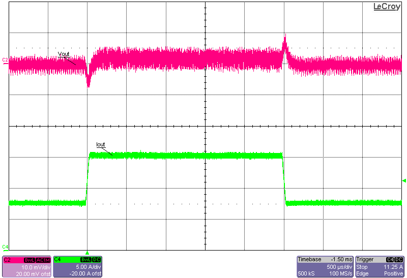
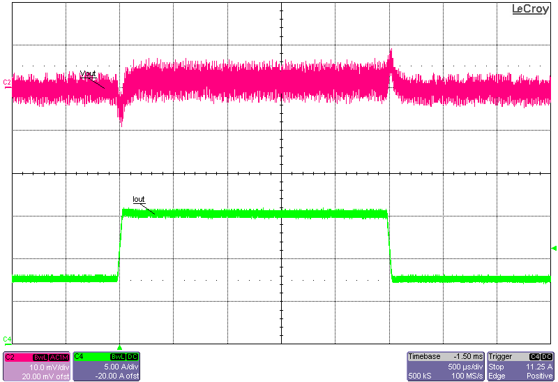
Figure 3-9 and Figure 3-10 show the load transient response of the converter at 12-V input and –0.2-V and –0.6-V outputs. The load is stepped from 50% to 100% of the load, corresponding to a 7.5-A to 15-A step.
 Figure 3-9 Load Transient Response, 12-V Input, –0.2-V
Output, 7.5-A to 15-A Load Step
 Figure 3-10 Load Transient Response, 12-V Input, –0.6-V
Output, 7.5-A to 15-A Load Step