SSZT432 July 2019 SN3257-Q1 , TMUX1072 , TMUX1511 , TMUX154E , TMUX1574 , TMUX1575
As boxer Mike Tyson once said, “Everybody has a plan until they get punched in the mouth.” Good boxers thrive when they can successfully throw their opponents off their game plan. Great boxers, however, are willing to get punched in the mouth and improvise until they can get back to their winning formula.
Similarly, system designers must improvise when faced with power-sequencing problems. Often, the simplest and most cost-efficient solution is to add a multiplexer with powered-off and fail-safe protection.
What Is Powered-off Protection?
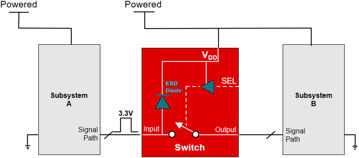
 Figure 1 Switch for Signal Isolation
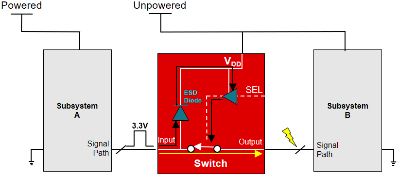
The open switch keeps the control signal at subsystem A until it is safe to pass the signal to subsystem B. Generally, the purpose of the switch is to dictate when to pass the control signal that may turn on critical parts of subsystem B. As straightforward as this sounds, the punch in the mouth happens when a timing mismatch unexpectedly occurs during power up and power down. In this case, the supply rail of subsystem A can power up before the switch and subsystem B, as shown in Figure 2.
 Figure 2 Back-powering During Power Sequencing
In contrast to Figure 1, the 3.3-V signal from subsystem A back-powers the internal electrostatic discharge diodes, turning the switch on. This closes the signal path to subsystem B, allowing the signal to leak through the switch (yellow arrow), resulting in a false logic state that can damage subsystem B and disrupt system startup.
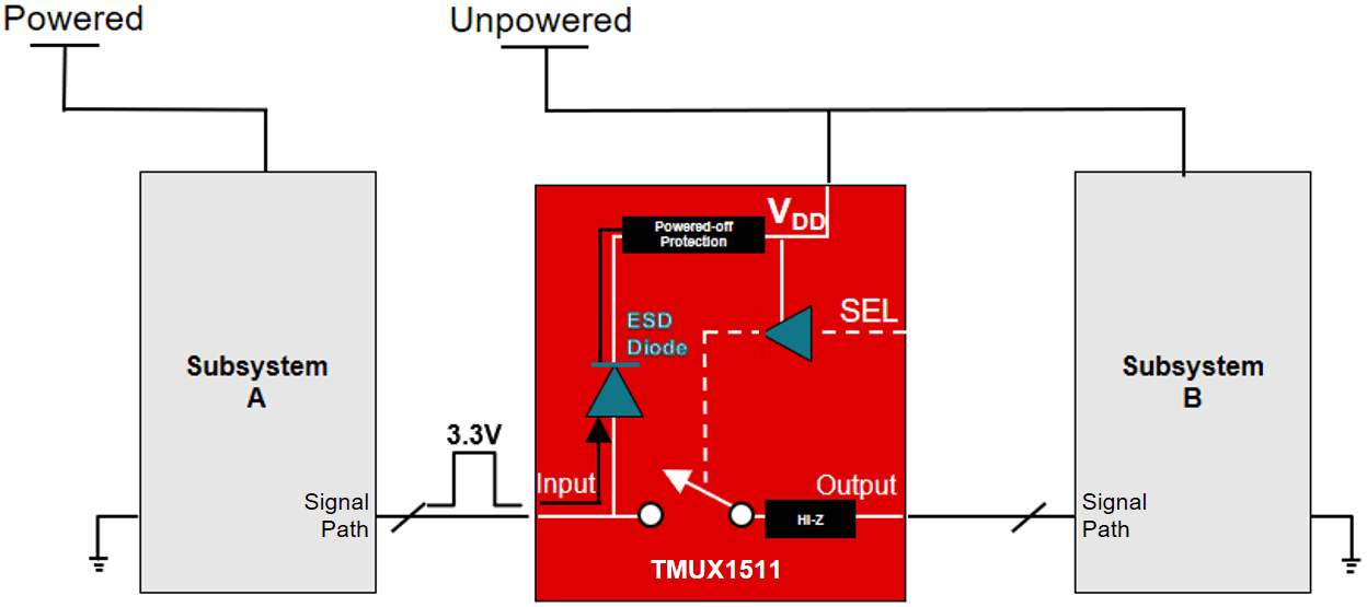
As a solution, TI powered-off protection switches maintain a high impedance state on the input/output (I/O) pins, preventing the unpowered supply rail (VDD) and the select (SEL) pin from back-powering.
Figure 3 shows the TMUX1511 successfully isolating the digital signal, protecting itself and subsystem B during power sequencing. Because of the powered-off protection feature, the switch is able to isolate the signal path from the power-supply rail. This adds a key layer of system protection because the switch can now isolate subsystems either powered or unpowered. Ultimately, this gives you a flexible method of solving power-sequencing complications by adding protection to the signal paths.
 Figure 3 TI Switches with Powered-off Protection
What about the Logic Signals in the SEL Pin?
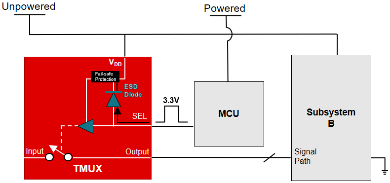
 Figure 4 Fail-safe Logic Switches Preventing Back-powering
Without fail-safe logic, the logic signal in the SEL or EN pin can back-power VDD, causing damage to subsystem B and the switch itself. Similar to powered-off protection, the switch maintains a high impedance state on the SEL logic pins, preventing power from going through VDD during power sequencing.
Choosing the Switch Right for You
Additional Resources
- Learn more about the protection features of the TMUX1072 in the TI training video, Multiplexers that protect from system overvoltage conditions.