SSZT066 august 2022 UCC21736-Q1 , UCC5870-Q1

As the demand for smart, automated and eco-friendly end-equipment continues to grow, industrial and automotive technologies are becoming increasingly electrified. With this trend also comes an increased emphasis on ensuring electronic systems not only meet standards of EV performance but safety standards as well. In the automotive space specifically, the use of highly-configurable isolated gate drivers in traction inverter systems is growing as a means to improve EV performance and streamline functional safety certification. As vehicle manufacturers pivot to electronic systems like traction inverters, so must the coverage of such systems by our safety standards.
While traditional "product safety" refers to the elimination of risk from electrical shock, fire and mechanical hazards, "functional safety" specifically refers to electrical and electronic system hazards. As technologies progress rapidly, many designers have to ramp up quickly on the broad world of functional safety. In this article, I’ll provide a general introduction to functional safety, along with examples relating to TI gate drivers and electric vehicle traction inverter systems.
| Enhance the Design of HEV/EV Traction Inverter Systems Using Isolated IGBT and SiC Gate Drivers | |

|
Read our application note to learn about designing traction inverter systems using TI isolated gate drivers, and the advantages of gate driver diagnostics and protection features. |
Clarifying Functional Safety Terms
In order to minimize equipment failures and personal injury, system designs and processes must address hardware faults in accordance with international standards. Common standards include International Organization for Standardization (ISO) 26262 (for automotive equipment) and International Electrotechnical Commission (IEC) 61508 (for industrial equipment).
There are two types of hardware faults:
- Systematic faults result from errors in the design or manufacturing process. Engineers can reduce systematic faults through continual process improvements.
- Random faults result from defects inherent to process or usage conditions. Engineers cannot fully eliminate random faults.
One of the goals of the ISO 26262 standard is to reduce the probability of random faults. Automotive Safety Integrity Levels (ASILs) represent the level of risk, with set probability thresholds. These levels range from ASIL A (least stringent) to ASIL D (most stringent). This standard further categorizes random faults into single-point and latent faults. Single-point faults violate safety goals without the presence of a safety mechanism. For example, an overvoltage lockout mechanism seeks to detect an overvoltage at the device output. A multiple-point failure is the result of several independent faults that directly violate a safety goal (multiple-point faults). A latent fault is a multiple-point fault whose presence is not detected by a safety mechanism nor perceived by the driver. For example, a fault occurring in the overvoltage lockout mechanism prevents it from detecting an overvoltage event. This is a latent fault if it is not detected by another safety mechanism (like a diagnostic test at start-up) or perceived by the driver; thus, stringent ASILs require monitoring and diagnostic circuits.
To help customers develop their functional safety system designs, TI functional safety products are developed per TI’s internal product development process (compliant to ISO 26262). For example, TI developed its first TI Functional Safety-Compliant isolated gate driver, the UCC5870-Q1, with applications such as traction inverters in mind. TI provides documentation to aid ISO 26262 system design up to ASIL D.
Leveraging Documentation for Functional Safety Analysis
TI’s portfolio of isolated gate drivers includes devices in each of the functional safety categories, from our least complex gate drivers which are TI Functional Safety-Capable to the most complex gate drivers being TI Functional Safety-Compliant. Each category provides different resources to assist designers in streamlining the certification process. Table 1 shows a table defining each category. Analytical resources may include:
- The failure-in-time (FIT) rate, an estimate of the number of failures that could occur in a billion cumulative hours of a product’s operation.
- Failure mode effects and diagnostic analysis (FMEDA), the probability of occurrence for failure modes and a quantified effectiveness of diagnostics.
- Fault-tree analysis (FTA), a qualitative analysis of random faults during operation.
| Functional Safety-Capable | Functional Safety Quality-Managed* | Functional Safety-Compliant* | ||
|---|---|---|---|---|
| Development Process | TI quality-managed process | X | X | X |
| TI functional safety process | X | |||
| Analysis Report | Functional safety FIT rate calculation | X | X | X |
| Failure mode distribution (FMD) and/or pin FMA** | X | Included in FMEDA | Included in FMEDA | |
| FMEDA | X | X | ||
| Fault-tree analysis (FTA)** | X | |||
| Diagnostics description | Functional safety manual | X | X | |
| Certification | Functional safety product certificate*** | X |
FIT rates are random hardware failure metrics. An example of this is the probabilistic metric for random hardware faults (PMHF). There are also fault metrics for both single-point faults (SPFM) and latent faults (LFM). ISO26262 defines acceptable FIT rate values for each ASIL. For example, ASIL D requires a SPFM of ≥99%, LFM of ≥90% and a PMHF of ≤10 FIT. ISO 26262 delineates two types of safety analysis—deductive and inductive. Deductive analysis, like FTA, is a top down approach. Inductive analysis, like FMEDA, is a bottom up approach. Vehicle manufacturers define their safety goals and address them at the vehicle level. TI’s functional safety documentation supports hardware analysis at the product level.
Identifying and Preparing for Traction Inverter Failure Modes
Traction inverter failure modes can have both mechanical and electronic causes. Functional safety designs focus on identifying the electronic causes and enabling corresponding safety mechanisms. For example, an undertorque event in a traction inverter system may originate from a mechanical cause or an electronic cause (such as a power transistor short circuit or damage to the gate driver). To prevent exposure to this type of risk, functional safety standards define ways to assess the risk level. With these guidelines in mind, functional safety system designs may include power transistor protection circuits and gate driver diagnostics.
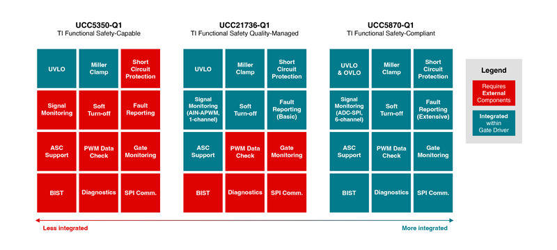
ISO 26262 standards allow functional safety system designs to use devices in each TI functional safety category. The protection and diagnostic circuits can be external or integrated into the gate driver. TI Functional Safety Quality-Managed (the mid-level functional safety category) gate drivers such as the UCC21736-Q1 have a basic set of integrated protection features. You can still consider these devices for functional safety system designs, but you may need to supplement the design with external circuitry. The UCC5870-Q1, a TI Functional Safety-Compliant isolated gate driver, integrates protection, diagnostics and fault reporting to streamline functional safety system designs. Figure 1 shows a comparison of three isolated gate drivers of different functional safety categories and varying levels of feature integration.
 Figure 1 A Comparison of Isolated Gate Drivers by TI Functional Safety Category and Level of Feature Integration.
To support this greater complexity, the UCC5870-Q1 includes built-in self-test (BIST) to prevent latent faults that protection features cannot detect. Much like TI Functional Safety-Compliant devices, the failure modes of traction inverter systems can also be quite complex. A failure mode such as an unintended motor shutdown can stem from the power-management IC, microcontroller, motor or gate driver, and ties into many required protection features. For example, each of these features integrated into the UCC5870-Q1 helps prevent exposure to torque disturbances:
- Undervoltage and overvoltage lockout.
- Desaturation detection and overcurrent protection.
- Two-level turnoff and soft turnoff.
- Collector-emitter voltage (VCE) monitoring and clamping.
- An analog-to-digital converter (to monitor voltages on the secondary (high-voltage) side of the gate driver, like power switch or gate driver temperature).
As systems grow more complex and electrified, so do the failure modes and management of random faults. To meet the needs of modern systems, the UCC5870-Q1 integrates protection features, diagnostics and fault reporting, with ISO 26262 and the requirements of (hybrid) electric vehicle traction inverters in mind.
Additional Resources
- Check out the TI functional safety overview page.
- Download the data sheet for the UCC5870-Q1.
- Read the application report, "HEV/EV Traction Inverter Design Guide Using Isolated IGBT and SiC Gate Drivers."