SPRACN7 September 2019 TMS320C5517 , TMS320C5517
2 Requirements
The following materials are required to run this demonstration:
- Hardware:
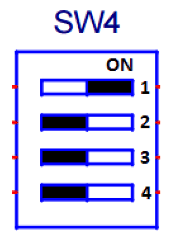
- Ensure that the correct dip switch settings are set for SW4 as illustrated below 1-ON, 2 to 4-OFF.
- TMDSEVM5517
- CMB
 Figure 2. SW4
 - Circular Mic Board (CMB) to C5517 EVM Connections
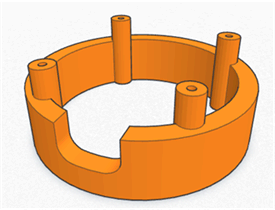
- Optional: Circular Mic Board (CMB) 3D print file for stand-off (http://software-dl.ti.com/public/download/CMB_Enclosure.zip)
Table 1. Power
CMB C5517 EVM CMB_3.3V J10_Pin9 3.3 V CMB_GND J10_Pin5 Ground Table 2. Signal for Mic1 and Mic2
CMB C5517 EVM CMB_SCL J14_Pin16 I2C SCL CMB_SDA J14_Pin20 I2C SDA CMB_BCLK J27_Pin3 (no jumper) Bit Clock CMB_LRCLK J27_Pin4 (no jumper) Frame Clock CMB_DATA1 J30_Pin2 (no jumper) Data 1 J29_Pin1_Pin3 (jumpber on) J29_Pin2_Pin4 (jumpber on) J30_Pin1_Pin3 (jumper on) Table 3. Signal for Mic5 and Mic6
CMB C5517 EVM I2X_USB_BCLK J27_Pin1 Bit Clock I2X_USB_LRCLK J27_Pin2 Frame Clock CMB_DATA2 J28_Pin2 Data 2 J28_Pin1_Pin (no jumper) J28_Pin2_Pin4 (no jumper) - Software
- C55x CSL (3.07.00 or greater)
- DSP/BIOS 5.42.02.10
- Code Composer Studio™ 6.1.3
- CGT for C5500 4.4.1
- XDCTools 3.24.05.48
- XDAIS 7.24.00.04
- AER 17.0.0.0 (C55x, CPU rev 3.3) (http://www.ti.com/tool/TELECOMLIB)
- VOLIB 2.1.0.1(C55x, CPU rev 3.3) (http://www.ti.com/tool/TELECOMLIB)
 Figure 3. CMB Standoff
 NOTE
In order to make the following build procedure to work, all above mentioned components have to be installed at the same location (ti/c55_lp by default).