SNOU143 February 2017 EMB1428Q , EMB1499Q
3 Theory of Operation
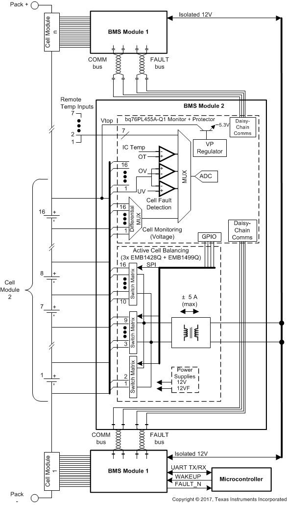
Figure 1 shows the system stack diagram.
 Figure 1. System Stack Diagram
 The BMS system is designed to prolong the useful life of Lithium-ion cells in battery packs through active balancing. The battery pack is broken into a series of modules, each of which contains up to 16 cells. This system will monitor voltages of individual battery cells and transfer charge from the module stack to an under-charged cell or take charge from an over-charged cell and transfer it to the module stack. The BMS allows battery powered electric machines to use smaller battery packs and use fewer charging cycles to perform the same amount of work. It also improves the overall lifetime of Li-ion battery packs by preventing under- and overvoltage damage from occurring.
The BMS system has three main sub-systems, as shown in Figure 1:
- Cell voltage monitoring circuitry
- Cell fault detection
- Active cell balancing engine
The cell-monitoring architecture is based on the bq76PL455A-Q1 (16 cell monitor and protection). Each EMB1428Q is designed to control access to up to 7 cells of a typical 16-cell battery module; the full 16-cell module utilizes three EMB1428Q and one to three EMB1499Q ICs. The EM1402EVM is designed with one EMB1499Q IC to allow simultaneous charge and discharge of a single cell (of the up to 16 cells attached) at up to 5 A.
All commands and data are communicated with a host via either a UART or daisy-chain communication connection. The EM1402 will not do anything without being first commanded from the host. The EM1402 can support a host PC or microcontroller (via the UART connection header) or a daisy-chain interface from a bq76PL455A-Q1 implemented as a communication bridge. The EMB1428Q is controlled via an SPI interface implemented on the bq76PL455A-Q1 GPIO.
The EM1402EVM has three EMB1428Q devices sharing control of a single EMB1499Q bi-directional DC-DC converter. The EM1402EVM has connected the cells the EMB1428Q devices as follows:
- EMB1428Q 1 (U2) : cells 1 and 2
- EMB1428Q 2 (U3) : cells 3 to 9
- EMB1428Q 3 (U4) : cells 10 to 16
The typical flow is for the host to go through the following sequence:
- Wakeup the EM1402 board by sending a WAKEUP pulse when using the UART interface, or sending a WAKE tone when using the EM1402 in a stack of other EM1402 boards for a large battery pack or a bq76PL455A-Q1 configured as a bridge. Initialize the bq76PL455A-Q1 to be ready for use.
- Send a sample command to the bq76PL455A-Q1 to read the cell measurement results.
- The host will use the cell measurement data to calculate an average and determine the highest or lowest cells and determine the one cell that should be charged or discharged.
- Send commands to the bq76PL455A-Q1 to initialize the EMB1428Q communication interface on the bq76PL455A-Q1 GPIO.
- Send commands to the bq76PL455A-Q1 to initialize the SN74AHC595Q I/O expander to enable the chip select for the 8-bit DAC on the EM1402EVM.
- Send commands to the bq76PL455A-Q1 to initialize the 8-bit DAC on the EM1402EVM which is used to set the charge or discharge current level (an input to EMB1499Q).
- Send commands to the bq76PL455A-Q1 to initialize the SN74AHC595Q I/O expander to enable the chip select for the EMB1428Q connected to the target cell (determined in step 3).
- Send commands to the bq76PL455A-Q1 to send the start command to the EMB1428Q to charge or discharge the target cell.
- When charge or discharge is to be stopped, send commands to the bq76PL455A-Q1 to send the stop command to the EMB1428Q to stop the charge or discharge of the target cell.
- If no stop command is sent, the EMB1499Q has a built-in timeout of 8 seconds, after which time the charge or discharge will be stopped automatically.
- If a longer amount of charge or discharge time is needed, the host will need to send a stop command, followed by a start command at least every <8 seconds.
- The host can then decide to repeat the process (back to step 2) or send commands to shutdown the EM1402EVM and return later.