SNLA398 October 2022 DS320PR810
3 EEPROM Programming Page
SigCon Architect can be used to generate an EEPROM file for a single redriver or multiple DS320PR810 redrivers. The below images provide an example.
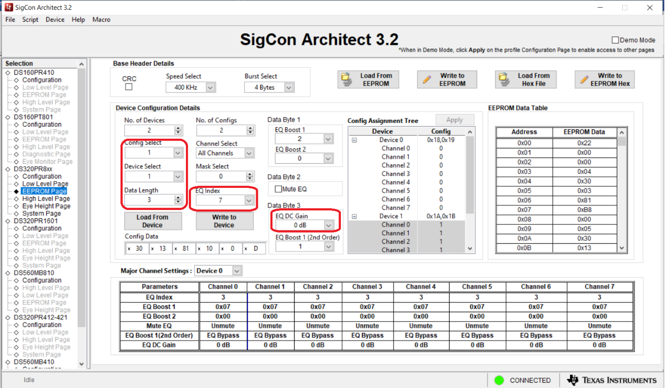
In this example, two redrivers are present with different EQ index values (CTLE index 3 for device at address 0x18, 0x19 and CTLE index 7 for device at address 0x1A, 0x1B), for each device, the same value is used for every channel. For programming additional devices, increase the number of devices and configs as needed.
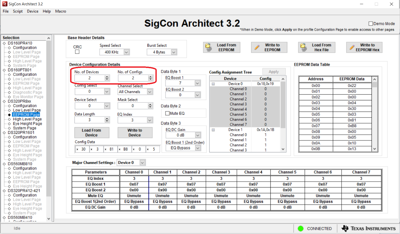
- Multiple devices can be
programmed at once. Select the number of devices and the number of
configurations. Up to 16 different configurations can be created and assigned to
each device and channel as needed.
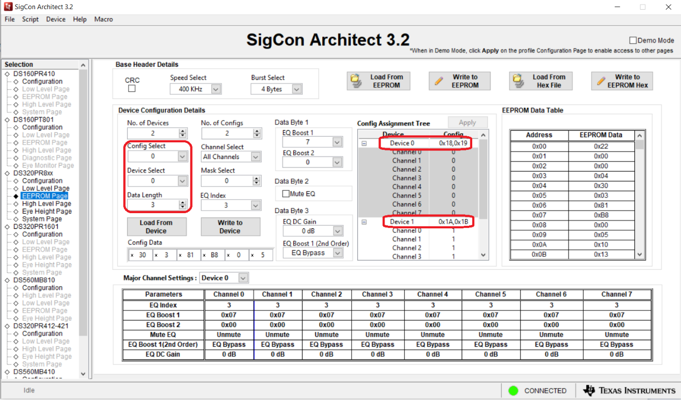
- To program the first device,
select configuration 0 and device 0 from the drop-down menu. Note the Config
Assignment Tree shows the hex address of each device (0x18, 0x19 for device 0).
Set the data length to 3 since 3 bytes are needed to program the DS320PR810.
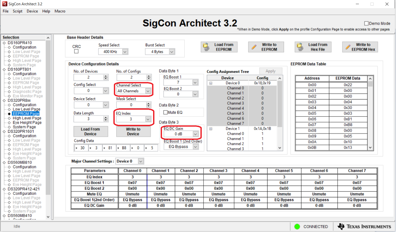
- Select the desired channel, then
choose an EQ Index from the drop-down menu. This will automatically
adjust the EQ boost 1, EQ boost 2, and EQ Boost 1 (2nd Order) fields. Select the
desired EQ DC gain. Note in the Config Assignment Tree that the desired channel
of device 0 will be applied with configuration 0.
- Switch to configuration 1 and
device 1 in the drop-down menu, set the data length back to 3, and select the
new EQ index, and DC gain. Notice the config assignment tree will update the
device 1 channels as config 1.
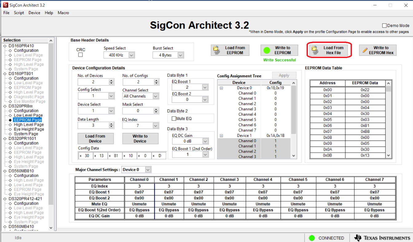
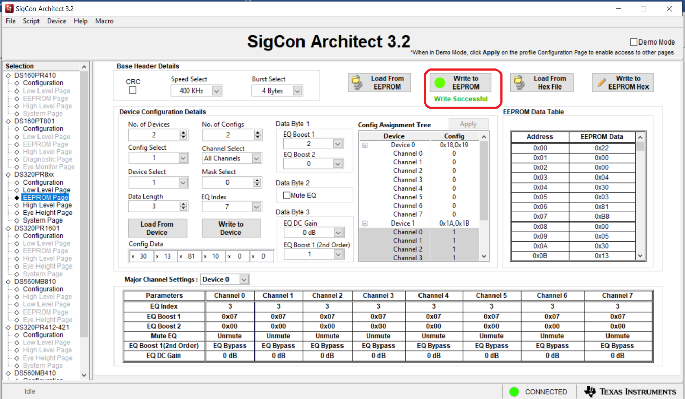
- Once all devices have been
configured, click the Write to EEPROM button to load the EEPROM with the
new settings. The button will turn green when the write is completed.
- To save these current EEPROM
settings for later, click the Write to EEPROM Hex button to create a hex
file with these settings. Save the hex file to the desired location.
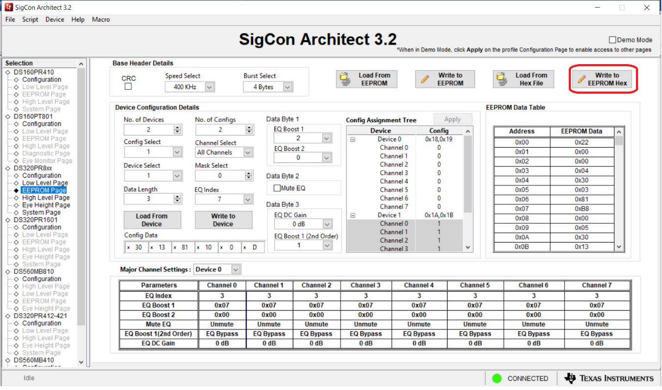
- To load the EEPROM settings back
from the hex file, click the Load from Hex File button, select the hex
file you saved, then click the Write to EEPROM button and wait for the
green dot.