SNLA398 October 2022 DS320PR810
6 System Page
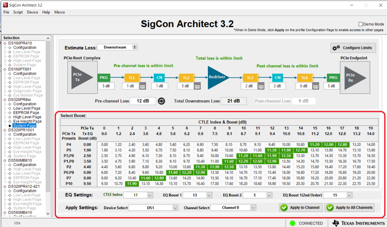
This page allows users to estimate optimal CTLE settings for their application, based on known pre and post channel losses. This feature is also available in Demo Mode.
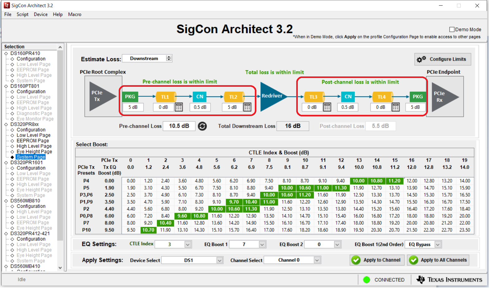
- Enter the known Pre and Post-channel losses into
each of the boxes. The GUI will show whether the losses are within the limit of
the redriver or not.
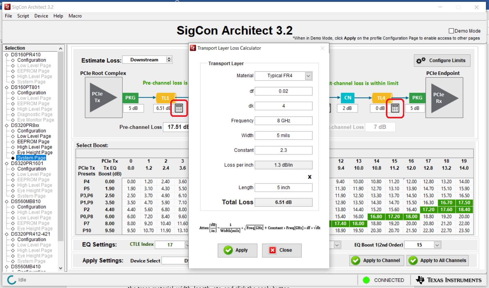
- Click the calculator button next to the
transmission lines to calculate loss for PCB traces. Enter the trace material,
width, length, and so on, and then click the Apply button.
- The table will highlight suggested CTLE values
for each PCIe Tx Preset, based on the losses you entered. You can use the lowest
part of the screen to apply these CTLE settings, or do it from the high-level
page. Note that these are only estimated values and are not guaranteed to be the
best settings. Further IBIS model simulation, or bit error rate testing can be
used to further determine the optimal redriver settings.