SLVAF75 August 2021 DRV10987
2.3 Implementing Option 1
To accurately implement sleep entry using Option 1, Step3 and Step4 must be performed in which Speed is a non-zero value, see Table 2-1.
In example code, Step1 and Step2 are skipped, because Step1 and Step3 are executed to run the motor at active state.
Table 2-1 Implementing C Code With Option 1
| DRV10987 Data Sheet | Implementation in C code | |
|---|---|---|
| Step1 | Provide a non-zero value to the speed control register. For example, write 100 to register 0x30, speedCtrl[8:0]. | |
| Step2 | Set the I 2C OverRide bit to 1. That is, write 1 to register 0x30, speedCtrl[15]. | |
| Step3 | In analog mode, be sure SPEED pin voltage is less than VEN_SL for tEN_SL_ANA. In PWM mode, make sure SPEED pin is low (V < VDIG_IL) for tEN_SL_PWM. |
|
| Step4 | Provide the value of zero to the speed control register to enter sleep mode. That is, write 0 to register 0x30, speedCtrl[8:0]. |
|
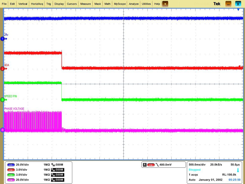
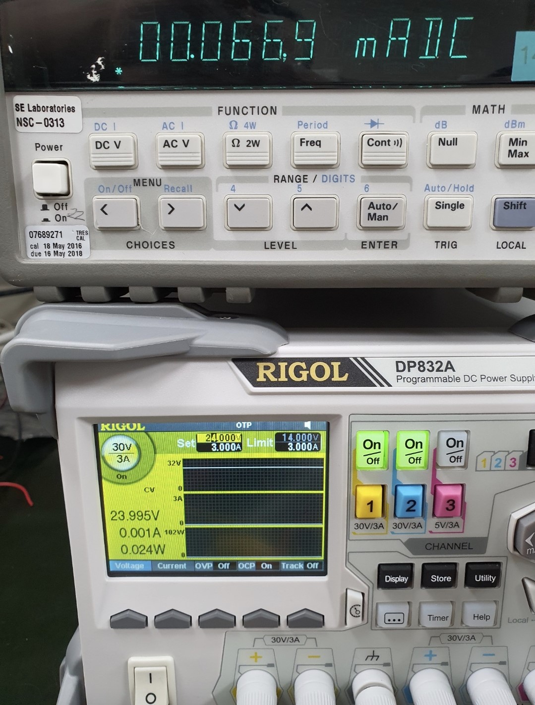
When DRV10987 enters sleep mode, 1.8 and 3.3 LDO are off and SDA that is pulled up with 3.3-V LDO is low. The current measured is 66.9 µA.

Ch1: 24 V, Ch2: SDA, Ch3: SPEED PIN Ch4: W PHASE VOLT of Motor
Figure 2-2 Waveform of Entering Sleep Using Option 1 Figure 2-3 Measure of Sleep Current