SLVAF75 August 2021 DRV10987
2.1 Hardware Setup
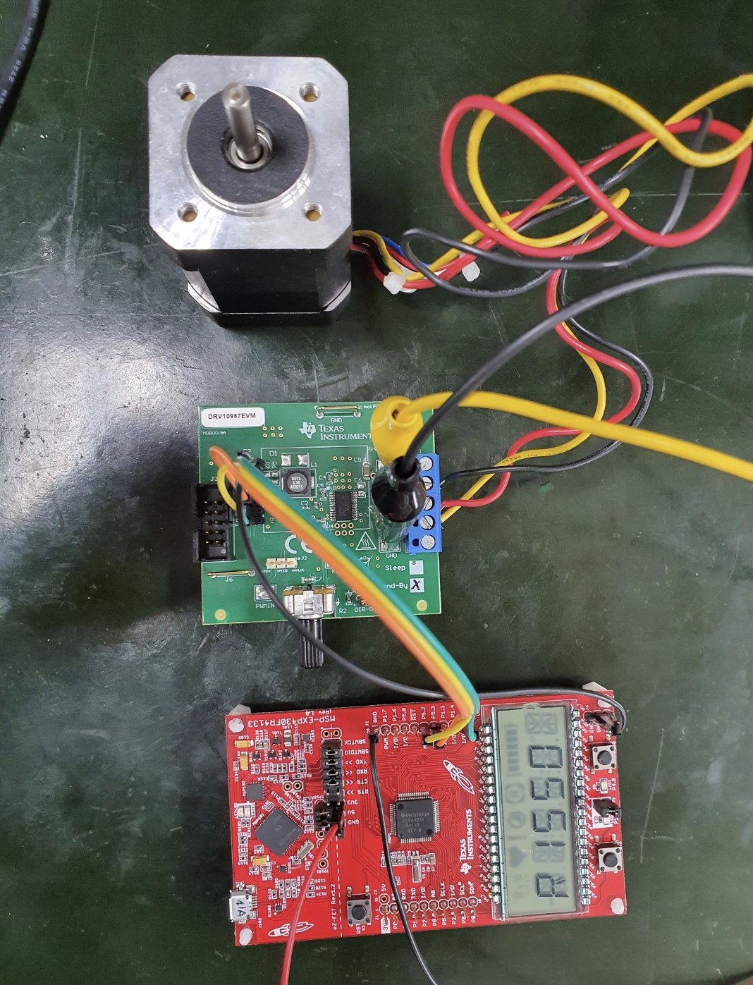
The DRV10987EVM and MSP-EXPFR4133 Development Kit are used. The following list shows the setup:
- VCC of the DRV10987EVM is connected to a 24-V power supply
- SD (SDA of I2C) of the DRV10987EVM is connected to the P5.2 pin of MSP-EXPFR4133
- SC (SDA of I2C) of the DRV10987EVM is connected to the P5.3 pin of MSP-EXPFR4133
- SPEED of the DRV10987EVM is connected to the P1.5 pin of MSP-EXPFR4133
Figure 2-1 displays the setup of the EVM and the development kit.
 Figure 2-1 DRV10987EVM and MSP-EXPFR4133 Development Kit Setup