SLVAF13 November 2020 LM5069 , TPS1663 , TPS2663
5 TPS16630 Parallel Circuit Configuration
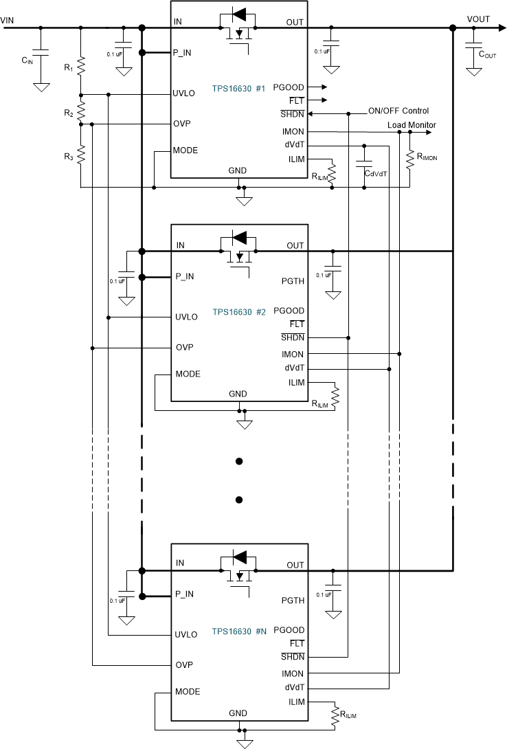
Figure 5-1 shows the parallel circuit configuration for TPS16630 devices. In this circuit, dv/dt start-up is considered, assuming that the system uses a large CdVdT value of > 470 nF where the mismatch in start-up currents between the devices is low. If equal current sharing during start-up is preferred, use the RILIM switch network at the ILIM pin of each device as discussed in Section 2 for TPS2663 device.
 Figure 5-1 Circuit Configuration of 'N'
TPS16630 Devices in Parallel