SLVA416A September 2010 – September 2021 DRV8424 , DRV8812 , DRV8813 , DRV8818
2.1 The Full Step
Bipolar stepper motors are often designed to be driven at full steps. However, it is a known fact that when each step is divided into multiple and smaller steps (referred to as micro steps), better motion quality can be observed. The application of microstepping to practically any stepper application allows for other improvements such as:
- Better torque response
- Less vibration
- Less resonance incidence
High resolution microstepping can be achieved by modulating the VREF analog inputs provided for current regulation setting in the driver. All which needs to be done is to apply an analog waveform to said reference voltage inputs, and the winding current magnitude will be regulated to follow the respective input. Generating this waveform can be accomplished by the using a DAC output such as the ones found on an MSP430 microcontroller. Putting all of this together gives us a series of advantages such as:
- Degrees of microstepping can be made as large as there is resolution on the DAC block. With a 12 bit DAC, you could have up to 4096 levels of microstepping. Far much more than most applications should require.
- Any waveform, however intricate, can be encoded into the VREF analog inputs. This could be used to resolve any magnetic non linearity within the stepper motor itself.
In this application note example we detail the mechanisms put in place to achieve high resolution microstepping by using a microcontroller, such as the MSP430F1612, in combination with a dual H-bridge DC motor driver with an output current regulation function. The same concept can be applied to two single H-bridge devices.
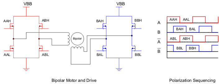
 Figure 2-1 Full Step
Stepper motors are brushless motors. In other words, they lack a brush making mechanical contact with a commutator, as housed on the typical brushed DC motor. Because of this, stepper motors must be electronically communicated. The most common way of communicating the rotor into motion is by modulating the magnetic field of each stator electromagnet.
There are two stator electromagnets on any conventional stepper motor, which is why two H Bridges are needed. By modulating both PHASE A and PHASE B pins, to obtain a polarization waveform such as the one depicted in Figure 2-1, the motor will move in full steps.