SLUUCE8A February 2021 – October 2021 UCC25800-Q1
- Trademarks
- 1 Description
- 2 Electrical Performance Specifications
- 3 Schematic Diagram
- 4 Description - How to Use
- 5 Test Setup
-
6 Performance Data and Typical Characteristic Curves
- 6.1 Efficiency Result of the LLC Board with External DC Input Voltage
- 6.2 Efficiency Result of the LLC Board with Pre-regulator on Board
- 6.3 Efficiency Typical Results
- 6.4 Output Characteristics
- 6.5 Output Voltage Turn-on at Start Up
- 6.6 Output Ripple Voltage
- 6.7 Frequency Synchronized to External Signal
- 6.8 DIS-pin Enable and Dis-Enable
- 6.9 Load Transient Response
- 6.10 Switch-node Voltage and Current
- 6.11 Over-Current Limit and FLT-pin
- 6.12 CISPR-25 Class-5 Conducted EMI Test Result - Pass
- 6.13 Thermal Images at Full Load
- 7 Transformer Details
- 8 EVM Assembly and Layout
- 9 List of Materials
- 10Revision History
6.9 Load Transient Response
Yellow = VOUT, DC coupled, Blue = Load Current, repetitive change between 50% (42.5mA) and 100% (85mA)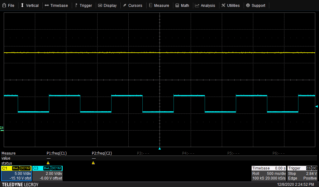 Figure 6-13 Load Transient Response, measured between TP6 and TP7 (a. no VOUT deviation observed due to the LDO; b. VOUT = 23V)
 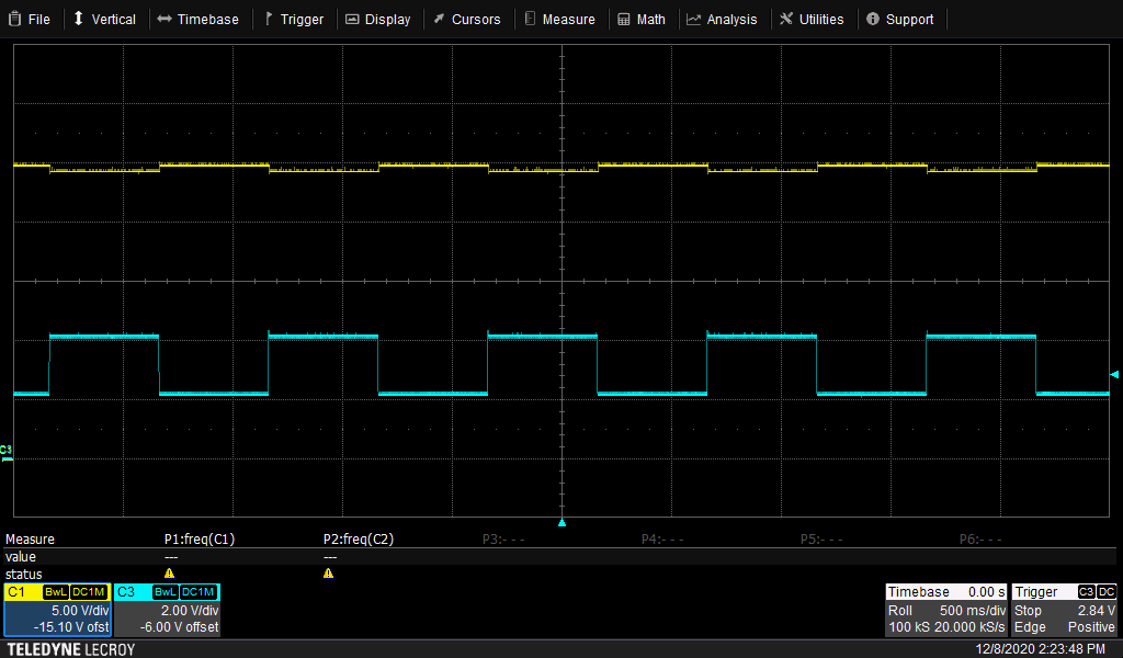 Figure 6-14 Load Transient Response, measured between TP4 and TP5 (a. VOUT deviation between 24.2V and 24.7V; b. VOUT = 24.4V)
Figure 6-13 Load Transient Response, measured between TP6 and TP7 (a. no VOUT deviation observed due to the LDO; b. VOUT = 23V) Figure 6-14 Load Transient Response, measured between TP4 and TP5 (a. VOUT deviation between 24.2V and 24.7V; b. VOUT = 24.4V)