SLUAAG6 June 2022 BQ25180
3 Test Results
This section shows some of the test results obtained with the
small form factor designs on the BQ2518x devices. Figure 3-1 shows the register map view of the BQ2518x chargers, while interacting with the
TI Chargers GUI using the USB2ANY as the
I2C interfacing device.
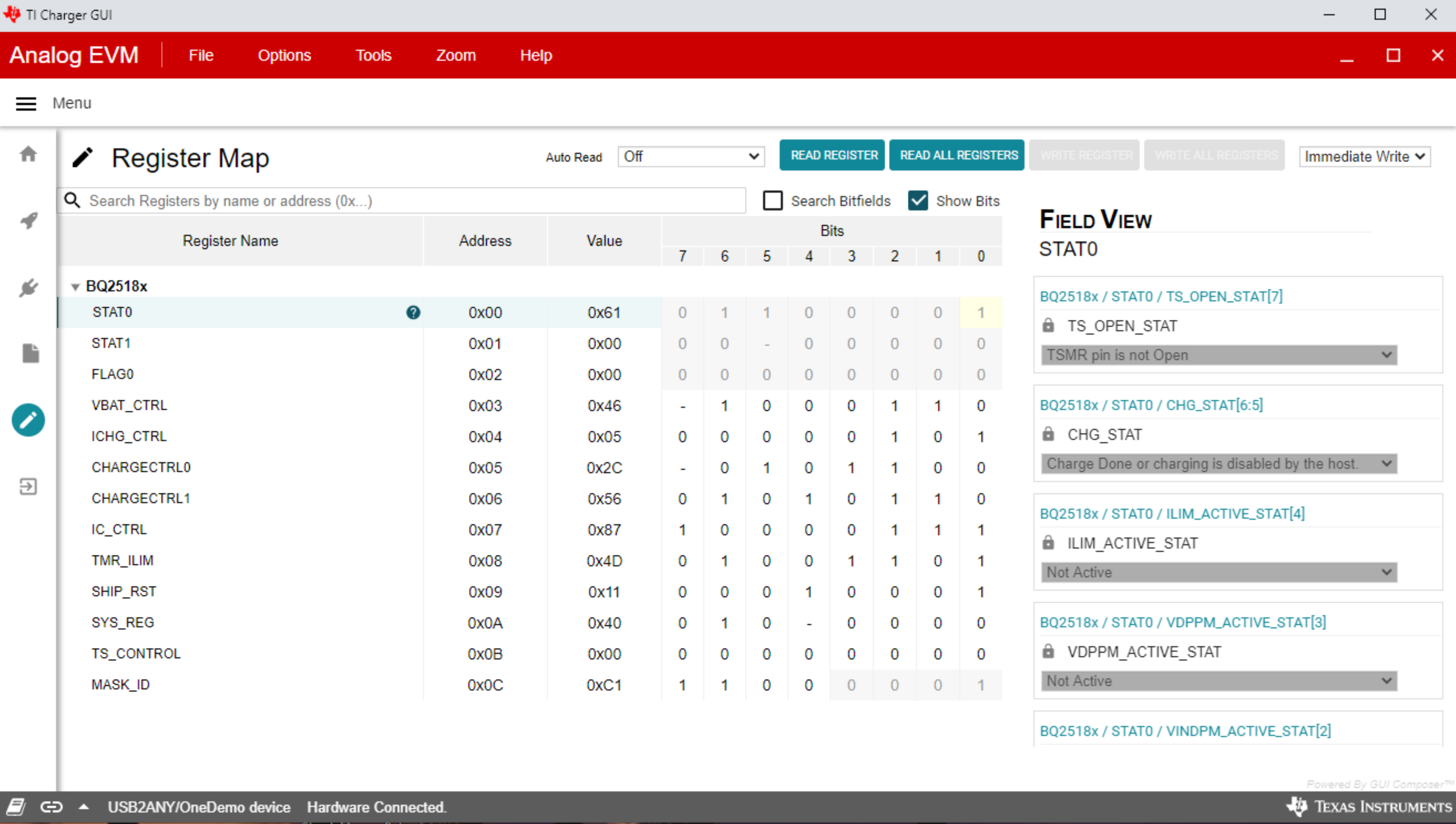
Figure 3-1 TI Chargers GUI Registers View
Figure 3-2 to Figure 3-9 shows the devices when power up via adapter, power up via battery, ship mode entry and wake with push-button input, and waking out of shutdown mode with adapter plug in.
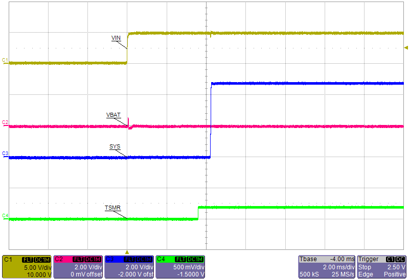 Figure 3-2 BQ25180 VIN
Applied
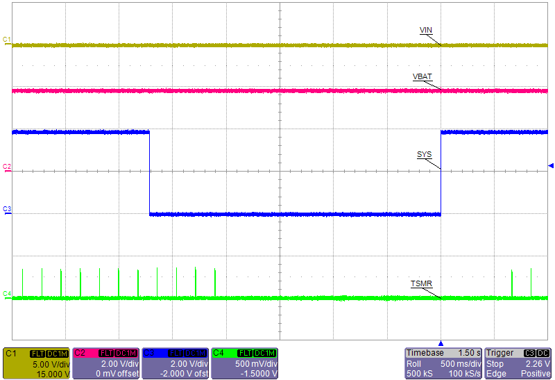 Figure 3-4 BQ25180 Shipmode Entry and
Exit with MR
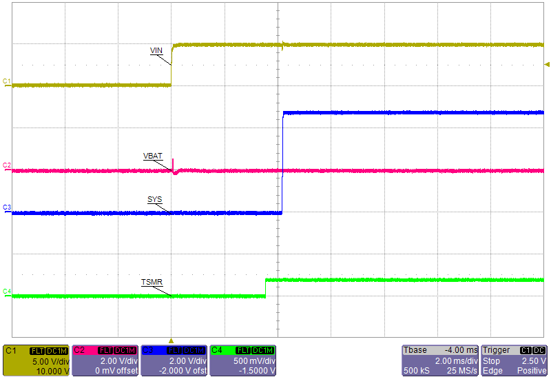 Figure 3-6 BQ25181 VIN
Applied
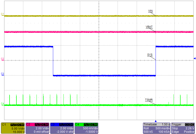 Figure 3-8 BQ25181 Shipmode Entry and
Exit with MR
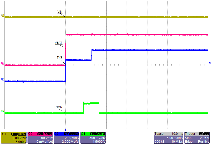 Figure 3-3 BQ25180 VBAT
Applied
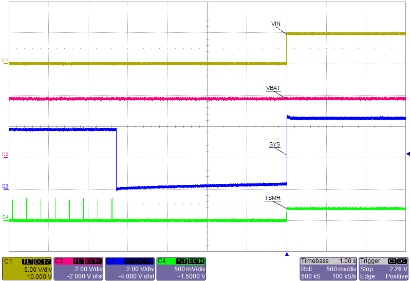 Figure 3-5 BQ25180 Shutdown Entry and
Exit with VIN Applied
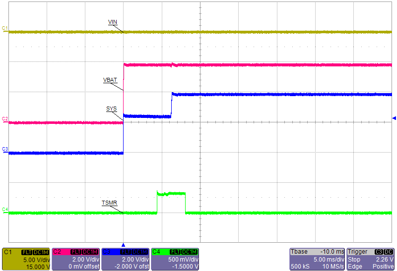 Figure 3-7 BQ25181 VBAT
Applied
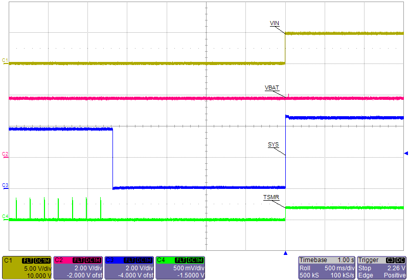 Figure 3-9 BQ25181 Shutdown Entry and
Exit with VIN Applied