SLUAAC0 September 2021 TPS92519-Q1 , TPS92520-Q1
1.2.1 Example Setup of Parallel Channels Generating 2-A Output Using TPS92520EVM-133 Board and GUI
Connect the LEDMCUEVM-132 to the TPS92520EVM-133, and connect the USB cable from the computer to the LEDMCUEVM-132. See instructions for GUI installation and operation that are in the TPS92520EVM-133 User’s Guide and the LEDMCUEVM-133 User’s Guide.
Start by selecting the En 520 No WD button to disable the watchdog timer (CMWEN bit in SYSCFG1 register). Before turning on the channels, use the GUI to set the channels to the desired set points for IADJ, TON, and so forth. In this example, Analog Current is set to 600 decimal, which is approximately 1 A for each channel. Both use the default On Time of 7 decimal which is approximately 440 kHz. See Figure 1-8.
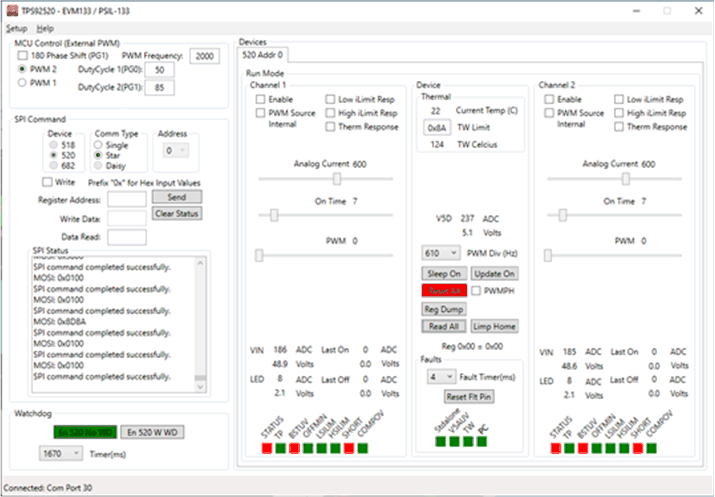 Figure 1-8 GUI After En 520 No WD
Button is Selected, Which Disabled the Watch Dog Timer
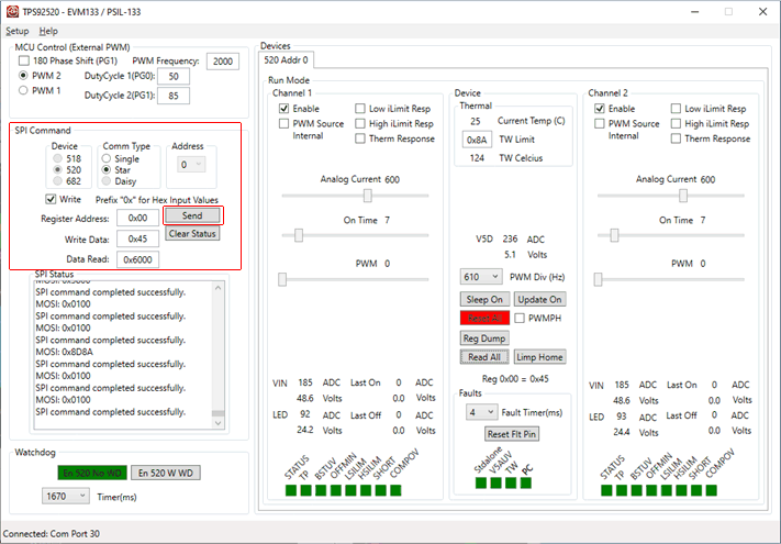 Figure 1-9 Using GUI to Write 0x45h to SYSCFG1 Register
at Address 0x00h
Figure 1-9 Using GUI to Write 0x45h to SYSCFG1 Register
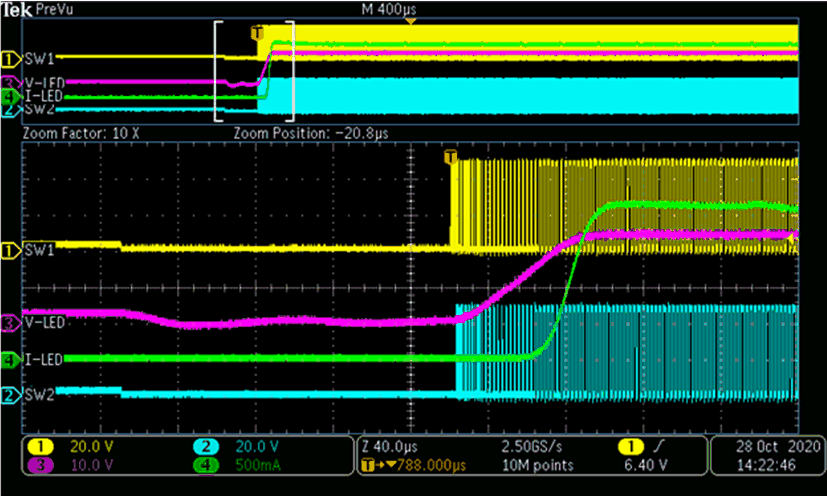
at Address 0x00hChannels 1 and 2 will then synchronously start-up and ramp up to 2 A at the outputs that are tied together. See Figure 1-10.
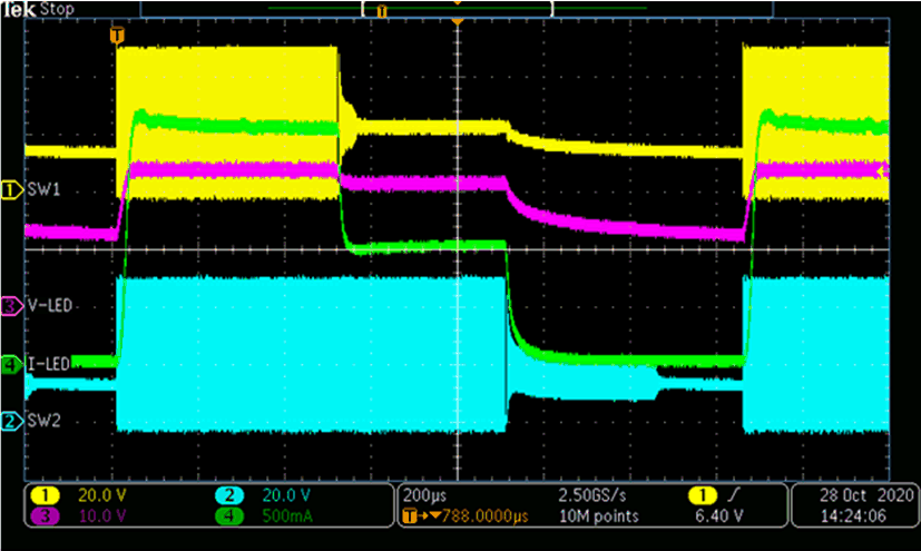
Internal PWM dimming can be used at this point because the PWMPH bit is set high (PWM phase between channels is 0). We can see each channel has different duty cycles setting. See Figure 1-11 for GUI setting and see Figure 1-12 for oscope screen shot of two channels on at different duty cycles.
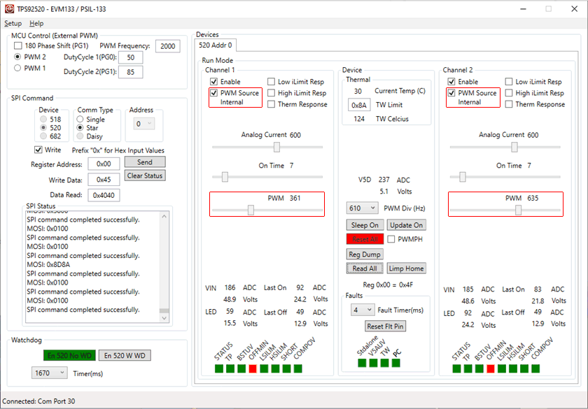 Figure 1-11 Parallel Channels Using Internal PWM Settings
Using the GUI