SLOU535 June 2019
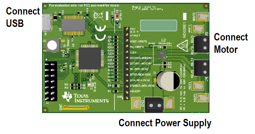
2.1 Connectors
The DRV8428x EVM supplies the VM (motor voltage) power rail through a reverse-battery protection circuit through the terminal block (J1). A set of test clips in parallel with the terminal block provide connections to monitor the input power rail.
The user must apply the VM voltage according to the recommended parameters listed in the datasheet (4.2 V to 33 V).
 Figure 2. Connections