SLLA575 June 2022 DRV10987 , MCF8316A , MCT8316A
2.1.3 Slow First Cycle
In slow first cycle start-up method, MCF8316A starts motor commutation at a frequency defined by SLOW_FIRST_CYCLE_FREQ. The frequency configured is used only for first cycle, and then the motor commutation follows acceleration profile configured by open loop acceleration coefficients A1 and A2. The slow first cycle frequency has to be configured to be slow enough to allow motor to synchronize with the commutation sequence.
Below are the dominant parameters that impact startup time during slow first cycle. Open loop parameters are discussed in Section 2.1.1.
- Frequency of first cycle [SLOW_FIRST_CYC_FREQ]
- Align or slow first cycle current limit [ALIGN_OR_SLOW_CURRENT_LIMIT]
Figure 2-9 shows the Q-axis current iqref and motor electrical frequency fele with respect to time.
During Slow first cycle, MCF8316A begins to accelerate the motor in open loop with the first cycle open loop frequency configured by FIRST_CYCLE_FREQ_SEL and ramps up the motor speed to the handoff frequency fele.
To minimize the motor startup time during slow first cycle operation, it is recommended to increase the frequency of first cycle [SLOW_FIRST_CYC_FREQ] and increase the align or slow first cycle current limit [ALIGN_OR_SLOW_CURRENT_LIMIT] to a value closer to the rated current of the motor.
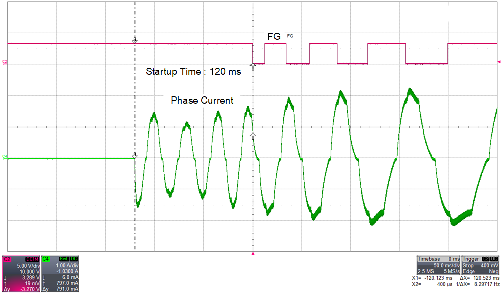
Figure 2-10 shows the FG and phase current of a BLDC motor. FG is configured to output pulses in closed loop. This is to know exactly at what point the motor enters closed loop. Time taken for the BLDC motor to enter closed loop is 120 ms.
 Figure 2-10 Time Taken to Enter Closed
Loop in Slow First Cycle