SLLA575 June 2022 DRV10987 , MCF8316A , MCT8316A
2.2.2 Manual Tuning
Kp and Ki coefficients can also be tuned manually by following below steps:
- Disable Speed loop by setting SPEED_LOOP_DIS to 1.
- Disable closed loop by setting CLOSED_LOOP_DIS to 1.
- Spin the motor in open loop by issuing non-zero speed command.
- Allow the open loop current to settle down and then measure the peak open loop phase current. Check the sign of the phase current by reading the Estimated Iq (register address: 0x000004E6).
- Enter 110% of measured peak phase current as the Iq reference in FORCE_IQ_REF_SPEED_LOOP_DIS. To convert Iq reference to FORCE_IQ_REF_SPEED_LOOP_DIS, see the MCF8316A Sensorless Field Oriented Control (FOC) Integrated FET BLDC Driver Data Sheet.
- Enable closed loop by setting CLOSED_LOOP_DIS to 0.
- Adjust the FORCE_IQ_REF_SPEED_LOOP_DIS such that the motor speed reaches the maximum speed.
- Calculate Speed loop Kp [SPD_LOOP_KP] and Speed loop Ki [SPD_LOOP_KI] using equation 1 and 2.
- Enable speed loop by setting SPEED_LOOP_DIS to 0.
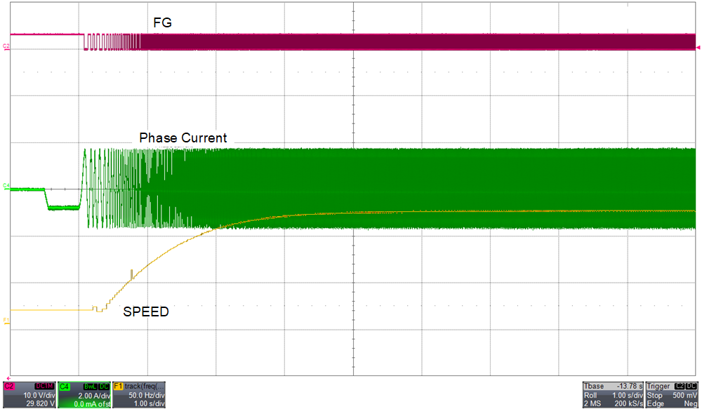
Figure 2-12 shows the FG, phase current and motor electrical speed in Hz with manually tuned Kp and Ki. Motor speed steadily ramps up to the target speed without any overshoots.
 Figure 2-12 FG, Phase Current and Motor
Electrical Speed in Hz With Manually Tuned Kp and Ki
Figure 2-12 FG, Phase Current and Motor
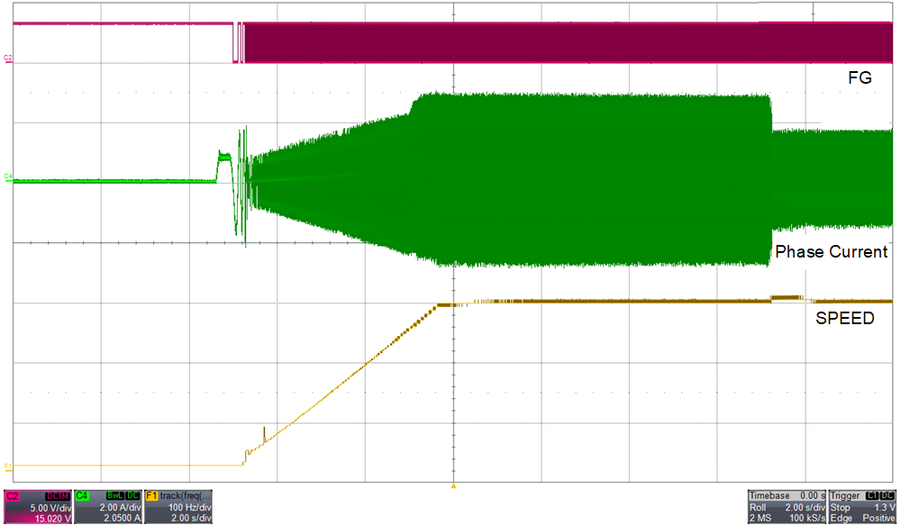
Electrical Speed in Hz With Manually Tuned Kp and KiFigure 2-13 shows FG, phase current and motor electrical speed in Hz when the phase current drops from 3A to 1.5A. With well-tuned speed controller Kp and Ki coefficients, speed slightly overshoots for less than a second and recovers back to the steady state speed.
 Figure 2-13 FG, Phase Current and Motor
Electrical Speed in Hz When the Phase Current Drops From 3A to 1.5A