SLIB006A February 2011 – June 2021 TPS81256 , TPS82084 , TPS82085 , TPS82130 , TPS82140 , TPS82150 , TPS82670 , TPS82671 , TPS826711 , TPS826716 , TPS82672 , TPS826721 , TPS82673 , TPS82674 , TPS826745 , TPS82675 , TPS82676 , TPS826765 , TPS82677 , TPS8268090 , TPS8268105 , TPS8268120 , TPS8268150 , TPS8268180 , TPS82692 , TPS82693 , TPS82695 , TPS826951 , TPS82697 , TPS82698 , TPS82740A , TPS82740B , TPSM82810 , TPSM82813 , TPSM82816 , TPSM82821 , TPSM82821A , TPSM82822 , TPSM82822A , TPSM82823 , TPSM82823A
2 MicroSiP Package
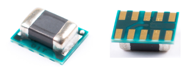
Within the MicroSiP family, there are two variations: MicroSiP (µSiP) and MicroSiL (µSiL). MicroSiP devices contain both the power inductor and one or more capacitors and typically use ball grid array (BGA) pins. MicroSiL devices contain just the power inductor and typically use land grid array (LGA) pins. The pin type difference creates different land pattern recommendations, but the SMT and rework guidelines remain the same for both packages. Figure 2-1 shows a typical MicroSiP with BGA pins, while Figure 2-2 shows a typical MicroSiL with LGA pins.

Figure 2-1 MicroSiP™ Package Integrates the Power Inductor and Two Capacitors and Uses BGA Pins

Figure 2-2 MicroSiL Package Integrates the Power Inductor and Uses LGA Pins