SLAU781 August 2018
2.3 LCD Interface Control
The K350QVG-V2-F-04 LCD supports for multiple interface modes:
- 8-, 9-, 16-, or 18-bit 8080 parallel interface
- 6-, 9-, 16-, or 18-bit RGB interface with 3-wire SPI
- 3-wire SPI
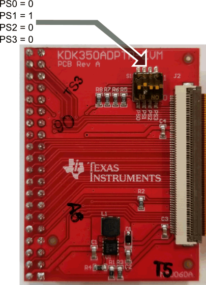
The mode is selected by the PS3, PS2, PS1, and PS0 pins on the LCD. Table 3 lists the selection for each mode. Switch bank S1 on the KDK350ADPTR-EVM controls the PS3, PS2, PS1, and PS0 pins (see Figure 3). The silkscreen adjacent to S1 shows the signal that each switch controls and the position to generate a 1 or a 0. Figure 3 shows the switch configuration to use 8080 16-bit parallel interface.
Table 3. LCD Interface Selection
| PS3 | PS2 | PS1 | PS0 | Interface |
|---|---|---|---|---|
| 0 | 0 | 1 | 0 | 16-bit 8080 parallel interface |
| 0 | 0 | 1 | 1 | 8-bit 8080 parallel interface |
| 0 | 1 | 0 | 0 | 9-bit RGB and 3-wire SPI |
| 0 | 1 | 0 | 1 | 16-bit RGB and 3-wire SPI |
| 0 | 1 | 1 | 0 | 18-bit RGB and 3-wire SPI |
| 0 | 1 | 1 | 1 | 6-bit RGB and 3-wire SPI |
| 1 | 0 | 1 | 0 | 18-bit 8080 parallel interface |
| 1 | 0 | 1 | 1 | 9-bit 8080 parallel interface |
| 1 | 1 | 1 | 0 | 3-wire SPI |
 Figure 3. Switch Bank S1 Configured to Use 8080 16-Bit Interface