SLAA936A September 2020 – March 2021 TAS2563
- Trademarks
- 1Introduction
-
2Quick Tuning Procedure
- 2.1 Initialize Tuning
- 2.2 Flatten Protection
- 2.3 Frequency Response Matching
- 2.4 Microphone Setup
- 2.5 Record Reference Device Response
- 2.6 Set Input Gain
- 2.7 Equalizer
- 2.8 Dynamic Range Compression (DRC)
- 2.9 Smart Amp Protection
- 2.10 Speaker Protection Verification
- 2.11 System Signal Chain
- 2.12 Tuning Elements
- 2.13 PDM MIC
- 3Related Documentation
- 4Revision History
2.13 PDM MIC
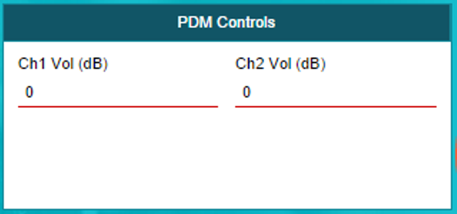
TAS2563 also supports 2 pcs PDM MIC recording and has 2 simple digital gains on the input signals.
The Maxim gain range is 30 dB (see Figure 2-32).
If you need this PDM MIC feature, you need a special version PPC3 Tool to support this feature.
 Figure 2-32 PDM Controls
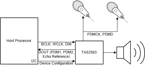
The System Block Diagram is like Figure 2-33.The Host Provide BCLK,WCLK,DIN to TAS2563 while TAS2563 transmit the PDM1 data,PDM2 data and Echo Reference to Host.
 Figure 2-33 Smart Amp Tuning
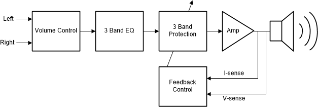
Figure 2-34 shows the speaker audio signal chain through the TAS2563 if you use PDM Mic version PPC3.
There are 3 bands EQ in the signal chain.
 Figure 2-34 Speaker Audio Signal
Chain