SLAA936A September 2020 – March 2021 TAS2563
- Trademarks
- 1Introduction
-
2Quick Tuning Procedure
- 2.1 Initialize Tuning
- 2.2 Flatten Protection
- 2.3 Frequency Response Matching
- 2.4 Microphone Setup
- 2.5 Record Reference Device Response
- 2.6 Set Input Gain
- 2.7 Equalizer
- 2.8 Dynamic Range Compression (DRC)
- 2.9 Smart Amp Protection
- 2.10 Speaker Protection Verification
- 2.11 System Signal Chain
- 2.12 Tuning Elements
- 2.13 PDM MIC
- 3Related Documentation
- 4Revision History
2.12.3.1 2-band DRC
The smart amp DRC available in the TAS2563 features two distinct bands separated by customizable first- or second-order filter crossovers and also enables configuration of typical compressor parameters such as threshold, ratio, attack, release, cutoff frequencies for each band, and global makeup gain (see Figure 2-17).
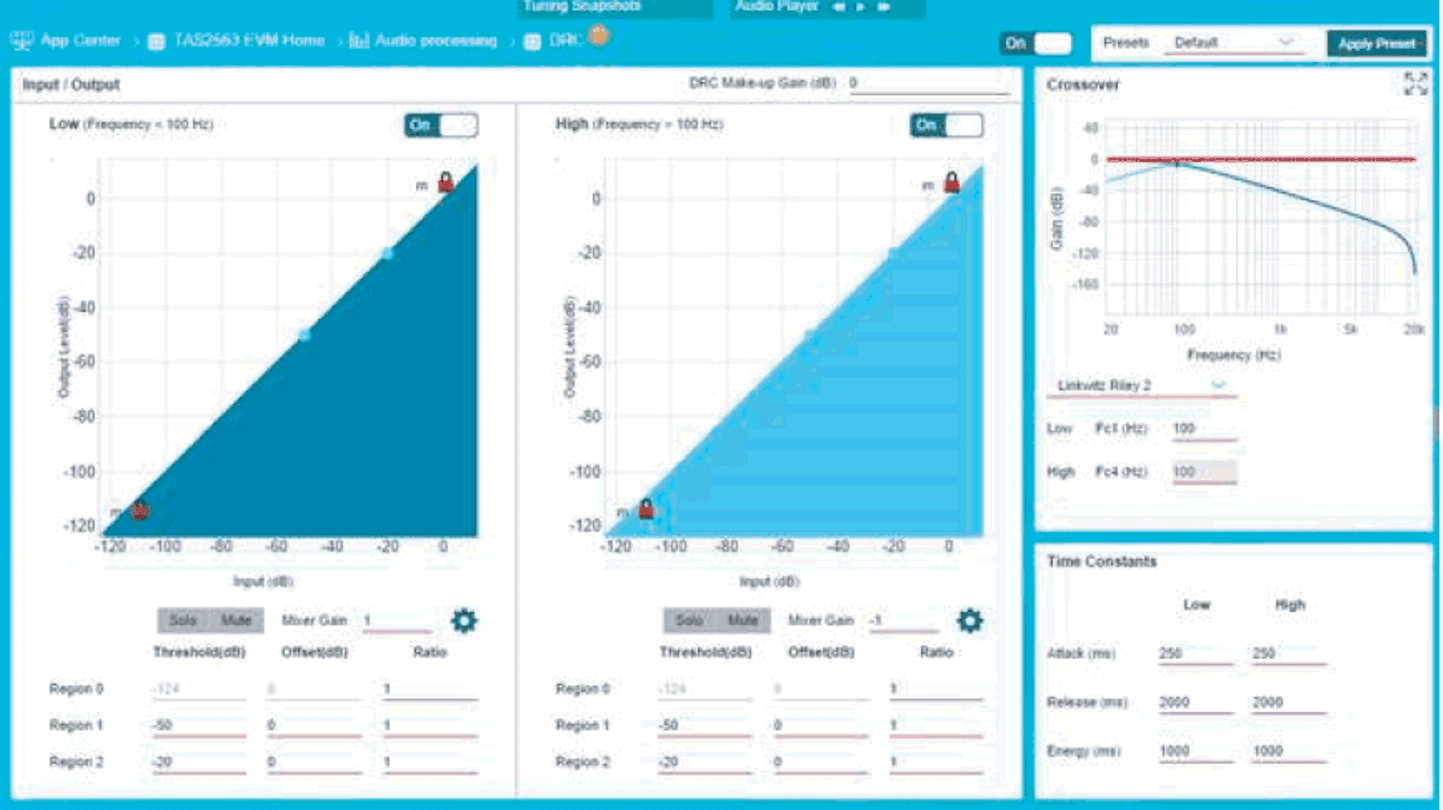 Figure 2-17 2-Band DRC Control
DRC is a very-powerful audio processing tool which is often used in several segments of the audio industry from professional studio and live environments to small audio electronics. Compression is the process of reducing the dynamic range of an audio signal by attenuating the loud signals and amplifying the soft signals. Compression can help to make audio sound louder without actually increasing the maximum output level of the signal. Because micro-speakers are subject to an excursion limit, but also have a reputation for low SPL output, DRC is a great tool to expand the apparent volume of the speaker sound while helping the protection block to limit the output signal level, and therefore, the excursion.
The typical procedure is to reduce the high-volume amplitude of the signal without affecting the low- volume portions of the signal. When these high-volume peaks are reduced, a makeup gain can be added to then increase the volume of the entire signal. In Figure 2-18, Figure 2-19, and Figure 2-20, signal A is the original, unprocessed audio track which has a few points of peak amplitude that prevent the entire track from being amplified without distortion. When these peaks are amplified past the full-scale value, they can often result in a distorted sound. Signal B shows the result after using a very harsh compression at –6 dB and, as a result, there is no signal content above –6 dB. Signal C then shows the result when signal B is amplified or normalized after the compression stage. Now the signal is at the maximum amplitude for the high-energy (loud) signals, but also the low-energy (quiet) parts of the track are louder than in signal A. If the compression is not too aggressive, the loss of volume in the peaks is negligible and unnoticeable, while the rest of the track sounds noticeably louder.
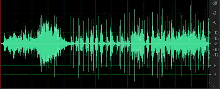 Figure 2-18 Typical Compression Sequence for Optimal Loudness—DRC Input, No Compression
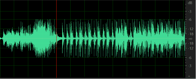 Figure 2-19 Typical Compression Sequence for Optimal Loudness—DRC Output, Compressed
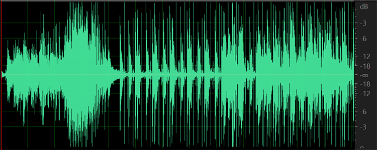 Figure 2-20 Typical Compression Sequence for Optimal Loudness—DRC Output, Compressed With Makeup Gain
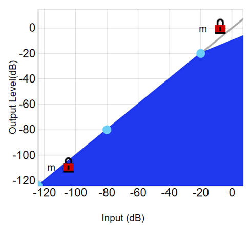 Figure 2-21 DRC Compression Ratio
Curve
Figure 2-21 DRC Compression Ratio
CurveThe following are useful terms for compression:
Threshold
The threshold is the input signal level above which the compression engages. Any input signal above this level has a reduced output level. Figure 2-21 shows a compression plot with the threshold at –20 dB. TI recommends a level of –20 dB with a ratio of 4:1; however, this value can result in reduced volume if a makeup gain is not in use. Also note the importance of being able to recognize an over- compressed sound. The target audience, and even the end user, will most likely be able to recognize this sound and it is always undesirable. Experiment with an extremely-low threshold and ratio such as –40 dB, 100:1 and become familiar with this sound to avoid it in the future. If the compression is too aggressive (low threshold and high ratio), it will sound over-compressed. If the compression is not aggressive enough (high threshold and low ratio), the output signal will feed into protection region and sound harsh.
Ratio
This term refers to the ratio of the input signal to output signal above the threshold. Ratio determines the amount of compression applied to the signal, which is denoted as input level:output level. A signal region unaffected by compression has a ratio of 1:1. A typical ratio can be 2:1 to 5:1. A 10:1 ratio or higher is an extreme case of compression known as a limiter. A limiter is useful for maximizing the output signal, but is often used after a compressor in the signal chain. The speaker protection region of the smart amp acts more like a limiter than a compressor.
Therefore, the DRC is useful to control and limit the dynamics of the signal with more variability and with a softer effect than the protection as to prevent a harsh sound while still maximizing the output level. When the ratio is less than 1, this is called expansion and this increases the gain of low-volume signals while leaving louder signals unaffected. shows a compression with ratio 2:1 above the threshold. When the input signal level is at 0 dB (full-scale), the output level is at –10 dB.
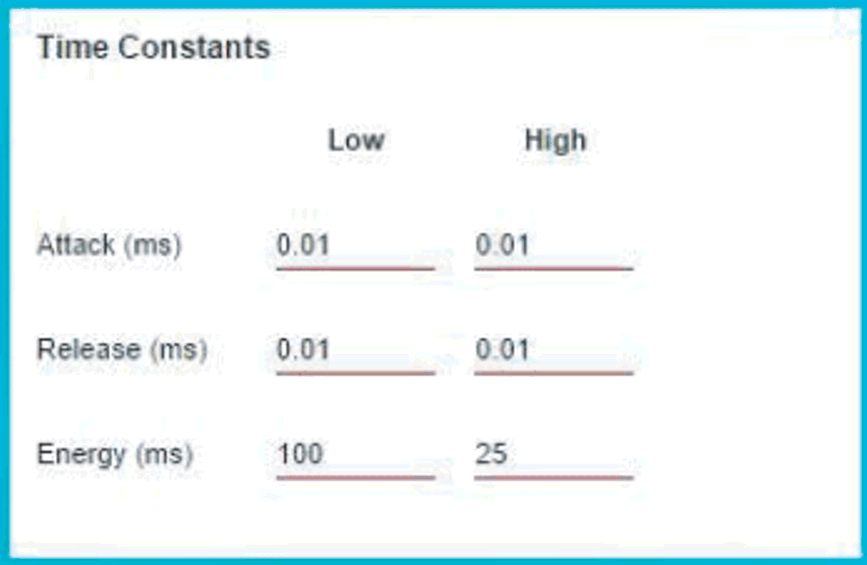 Figure 2-22 DRC Time Constant Controls
Attack, release, and energy time constants
These controls introduce a degree of control over how quickly the compressor reacts to the input signal. The DRC requires a good estimation of the input signal to function. The DRC is estimated in three steps. The energy time constant calculates the level of the input signal. Next, the input and output relationship is calculated, and finally the DRC control signal is smoothed by the attack and release times. The attack time determines the amount of time to reduce the signal gain after the input signal level has surpassed the threshold level. When the input signal has fallen back below the threshold, the release time determines the time to bring the output signal back up to its original gain.
The recommended values for time constants in the smart amp DRC are 10 / flow for the energy, where flow is the low cutoff frequency of the DRC crossover band filter and 0.01 ms for the attack and release time (see Figure 2-22). For example, if the mid-band-crossover low cutoff is 400 Hz, then set the energy time for the mid-band to 25 ms and the attack and release to 0.01 ms. The user can set the energy for the low-band to 100 ms. The energy time constant, which is not seen in a typical compressor, introduces a delay in the reaction time of the compressor much like attack and release delays. For this reason, the attack and release times are often not required in this DRC, but are available to add additional reaction control.
Makeup gain
This gain stage is at the end of the DRC signal chain and is a global gain for the entire audio band. The user may occasionally find benefits in increasing the post-attenuation signal to maximize the output signal and create the apparent volume discussed earlier because one function of the compressor is to attenuate and control high-volume signals to shape and reduce the dynamic range of the whole sound. Making this increase is not always the case in a smart amp design like this because the DRC is followed by the protection stage, which acts like a low-latency limiter. TI recommends to try and balance SPL optimization while also avoiding the protection stage as much as possible. TI also recommends a typical makeup gain of 0 dB to 2 dB. Experiment with balancing the makeup gain with the full-chain input gain from earlier. Sometimes just reducing the input gain and increasing the makeup gain can create a well-balanced, clean, and loud sound. Be sure to note, however, that the makeup stage inherently increases the low-volume output level and therefore, enhances noise.
Crossover and multi-band compression
The more primitive compression tools use only a single band for the entire frequency spectrum; however, the smart amp DRC enables a commonly-used professional audio tool called multi-band compression. More bands means more control over the input signal to optimize the sound quality and SPL. Using more bands also allows for high-volume sound shaping in addition to the EQ. For instance, a user can implement a more aggressive high-band compression to reduce certain shrill, high-end sounds in loud input signals or to accentuate the low-end bass region. In the TAS2563 device, the audio signal originating from the EQ block output is split into three bands using customizable crossover filters. The default values of 400 Hz and 4000 Hz are recommended. However, because the resonance frequency is often in the 700- to 1000-Hz range, another option is to place the low-band cutoff higher than the resonance frequency and use the low-band DRC to control the overexcursion from resonance. The crossover frequencies must always be equal. For example, the low-band cutoff must equal the mid-band low cutoff.
The DRC page offers a global enable button . Additionally, each band has an enable button which only bypasses the compression for that band but does not mute the signal from that band. Use the solo and mute buttons below the input and output curve to isolate one band to focus on the compression results. Use the enable buttons to hear the effect of the DRC on the audio quality. Figure 2-23 shows the DRC filter crossover. Figure 2-24 shows the DRC makeup gain control.
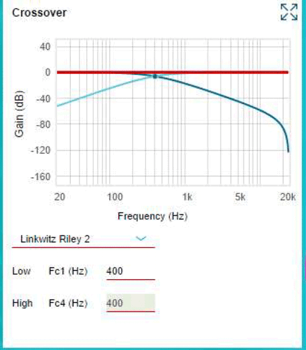 Figure 2-23 DRC Crossover Filter Controls
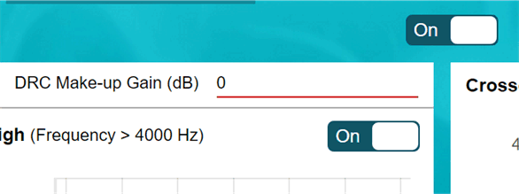 Figure 2-24 DRC Makeup Gain
Ganged DRC
For stereo applications, where the two-speaker responses are identical, TI usually recommends to gang the DRC for channels A and B in dual mono mode. This ganged DRC configuration indicates that when the input signal level of either channel reaches the threshold value, both channel gains are reduced simultaneously, which enhances the sensation of stereo sound. In some audio tracks, one side of the stereo image is much louder due to panning. Without ganging the two channels, the DRC only reduces the loud side and leaves the quiet side unmodified, which can create unwanted artifacts in the stereo image and disorientation in the listener. If the two speakers are not identical and have very different responses, ganged DRC can also cause negative artifacts in the sound and is usually not recommended. Find the gang feature at the top-right of the DRC page.
Noise gate
Another useful feature of the DRC and a common tool in professional audio is the noise gate. The purpose of the noise gate is to reduce unwanted, low-volume noise by attenuating any signal below a set noise gate threshold. The gain curve in Figure 2-25 shows the effective response of the noise gate and also shows another way to implement the noise gate. The noise gate can help to create the effective sound of a higher-dynamic range by reducing the small-signal response. Experiment with a solo drum track and make an extreme noise gate of a –30-dB threshold and –100-dB attenuation to understand the effect of this feature.
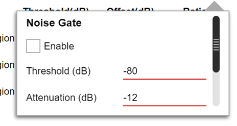 Figure 2-25 Automatic Noise Gate Control
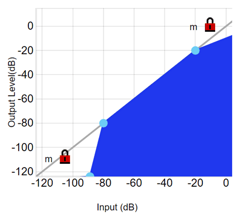 Figure 2-26 Manual Noise Gate Setting