SBOA442 March 2021 TMP107 , TMP107-Q1
2 CAN and RS-485 Physical Layers
Although the SMAART wire bus interface is proven to be reliable, both the CAN and RS-485 physical layers offer a significant improvement in noisy environments due to differential signaling. The difference between the CAN and RS-485 transceiver is the way they drive the bus.
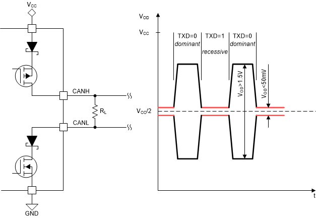
The CAN transceiver uses an open collector output and does not require any driver enable signal. Multiple transceivers transmitting at the same time ruin data integrity but there is not any excessive current flowing through the bus. The CAN bus defines a recessive and dominant state on the bus. These states represent logic values zero or one. Figure 2-1 shows the fundamentals. See the blog article [1] for further details.
 Figure 2-1 Fundamentals of the CAN
bus
Figure 2-1 Fundamentals of the CAN
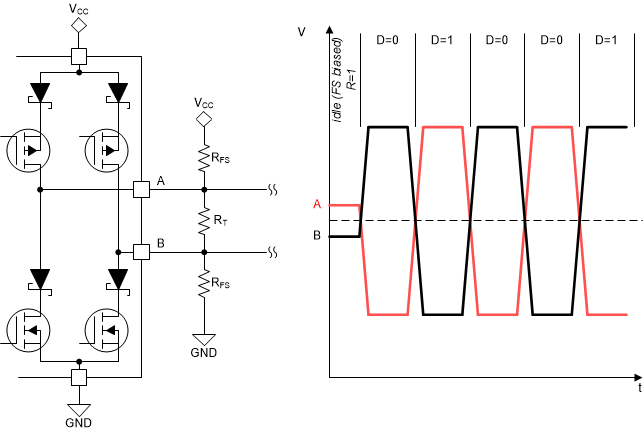
buslogic 1. Lower voltage on the node A than B represents logic 0.
Multiple RS-485 transceivers transmitting at the same time cause bus contention. One transceiver may force the signal line high whereas the second forces it low. Modern transceivers use protections but this unwanted event causes excessive power dissipation and ruins data integrity. Figure 2-2 shows fundamentals of the RS-485 bus. See the blog[2] for additional information on RS-485 bus.
 Figure 2-2 Fundamentals of the RS-485
bus