SBAA288A July 2018 – January 2019 ADS7142
5.1 Manual Mode
At power up, the ADS7142 goes into manual mode. In this mode, the device uses the high frequency oscillator for conversions. This mode allows the external host processor to directly request and control when the data is sampled. The resolution is set to 12 bits and samples are clocked out by providing continuous SCL when the desired channels are selected.
If the device scans both channels in AUTO sequence, the first data (sample A) is from CH0 and second data (sample A+1) is from CH1. The main routine for manual mode operation with AutoSequencing of both channels is as follows:
#include "ADS7142RegisterMap.h"

/*
ADS7142_ManualMode_AutoSequencing_CH0_CH1_Scan.c
*/

int main(void)
{

//Initialize the master MCU (0 = 100 kHz SCL, 1 = 400 kHz SCL)
TM4C1294Init(0);

//Calibrate out the offset of the ADS7142
ADS7142Calibrate();

//Let's put the ADS7142 into Manual Mode with both Channels enabled in Single-Ended Configuration for AUTO Sequencing

//Select the channel input configuration
ADS7142SingleRegisterWrite(ADS7142_REG_CHANNEL_INPUT_CFG, ADS7142_VAL_CHANNEL_INPUT_CFG_2_CHANNEL_SINGLE_ENDED);

//Confirm the input channel configuration
uint32_t channelconfig;
ADS7142SingleRegisterRead(ADS7142_REG_CHANNEL_INPUT_CFG, &channelconfig);

//Select the operation mode of the device
ADS7142SingleRegisterWrite(ADS7142_REG_OPMODE_SEL, ADS7142_VAL_OPMODE_SEL_I2C_CMD_MODE_W_AUTO_SEQ_EN);

//Confirm the operation mode selection
uint32_t opmodeselconfig;
ADS7142SingleRegisterRead(ADS7142_REG_OPMODE_SEL, &opmodeselconfig);

//Set the I2C Mode to High Speed (optional)
//ADS7142HighSpeedEnable(ADS7142_VAL_OPMODE_I2CMODE_HS_1);

//Check the I2C Mode Status
uint32_t opmodei2cconfig;
ADS7142SingleRegisterRead(ADS7142_REG_OPMODE_I2CMODE_STATUS, &opmodei2cconfig);

//Configure Auto Sequencing for both channels
ADS7142SingleRegisterWrite(ADS7142_REG_AUTO_SEQ_CHEN, ADS7142_VAL_AUTO_SEQ_CHENAUTO_SEQ_CH0_CH1);

//Confirm Auto Sequencing Register Configuration
uint32_t autoseqchenconfig;
ADS7142SingleRegisterRead(ADS7142_REG_AUTO_SEQ_CHEN, &autoseqchenconfig);

//Set SEQ_START Bit to start the sampling Sequence
ADS7142SingleRegisterWrite(ADS7142_REG_START_SEQUENCE, ADS7142_VAL_START_SEQUENCE);

//Begin manual mode operation with AUTO Sequencing

//Start Sampling Ch0 and Ch1
while (ADS7142DataRead_continuous() < 0 );

//Return no errors
return(0);

}
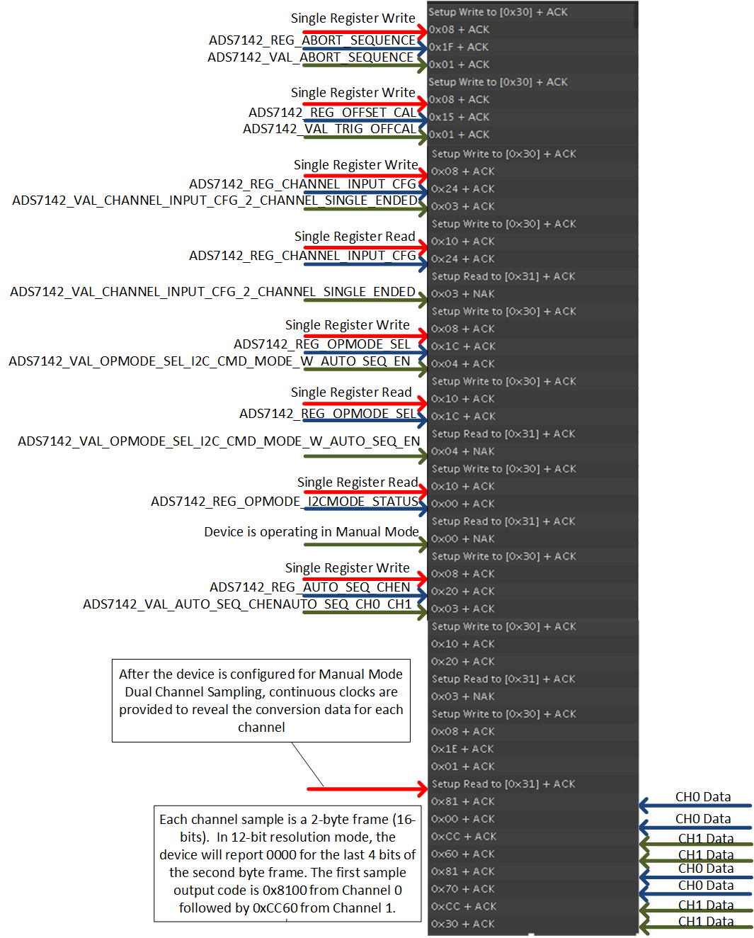
The I2C address of the ADS7142 is a 7-bit address followed by a read/write bit indicating the direction of data transfer. The I2C address of the ADS7142 is set to 0x18 (001 1000 R/W) by the hardware configuration of the ADS7142BoosterPack™. The analyzer sees an 8-bit address with the R/W bit as part of the address, and therefore reports the I2C address as 0x30 (0011 0000) for a write operation and 0x31 (0011 0001) for a read operation. Figure 14 illustrates the test data from the salae logic analyzer.
Masks that contain the letters REG refer to ADS7142 register masks, and masks that contain the letters VAL refer to ADS7142 value masks.
 Figure 14. Manual Mode Dual Channel Sampling Test Data