SBAA288A July 2018 – January 2019 ADS7142
5.4 Autonomous Mode With Start Burst Data
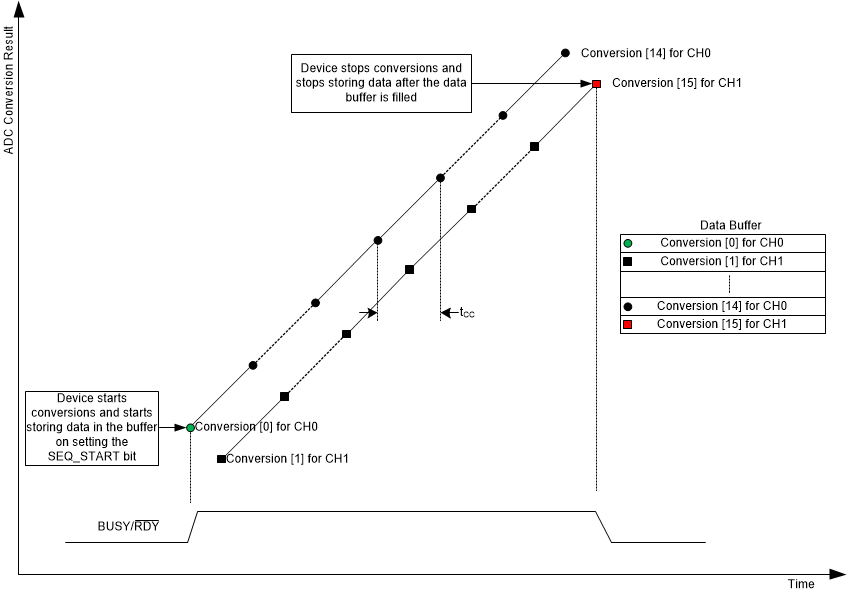
In autonomous mode with start burst data functional mode, the ADS7142 can be configured to start filling the data buffer when starting the conversion sequence. After the data buffer is filled, conversion stops. Figure 25 shows how this functional mode handles conversions.
 Figure 25. Start Burst With Dual-Channel Configuration
 The main routine is the following:
#include "ADS7142RegisterMap.h"
/* *ADS7142_AutonomousMode_StartBurst_AutoSequencing_CH0_CH1_Scan.c */

int main(void)
{

//Initialize the master MCU (0 = 100 kHz SCL, 1 = 400 kHz SCL)
TM4C1294Init(0);

//Calibrate out the offset from the ADS7142
ADS7142Calibrate();

//Let's put the ADS7142 into Autonomous Mode with both Channels enabled in Single-Ended Configuration

//Select the channel input configuration
ADS7142SingleRegisterWrite(ADS7142_REG_CHANNEL_INPUT_CFG, ADS7142_VAL_CHANNEL_INPUT_CFG_2_CHANNEL_SINGLE_ENDED);

//Confirm the input channel configuration
uint32_t channelconfig;
ADS7142SingleRegisterRead(ADS7142_REG_CHANNEL_INPUT_CFG, &channelconfig);

//Select the operation mode of the device
ADS7142SingleRegisterWrite(ADS7142_REG_OPMODE_SEL, ADS7142_VAL_OPMODE_SEL_AUTONOMOUS_MONITORING_MODE);

//Confirm the operation mode selection
uint32_t opmodeselconfig;
ADS7142SingleRegisterRead(ADS7142_REG_OPMODE_SEL, &opmodeselconfig);

//Set the I2C Mode to High Speed (optional)
//ADS7142HighSpeedEnable(ADS7142_VAL_OPMODE_I2CMODE_HS_1);

//Check the I2C Mode Status
uint32_t opmodei2cconfig;
ADS7142SingleRegisterRead(ADS7142_REG_OPMODE_I2CMODE_STATUS, &opmodei2cconfig);

//Select both channels for AUTO Sequencing
ADS7142SingleRegisterWrite(ADS7142_REG_AUTO_SEQ_CHEN, ADS7142_VAL_AUTO_SEQ_CHENAUTO_SEQ_CH0_CH1);

//Confirm Auto Sequencing is enabled
uint32_t autoseqchenconfig;
ADS7142SingleRegisterRead(ADS7142_REG_AUTO_SEQ_CHEN, &autoseqchenconfig);

//Select the Low Power or High Speed Oscillator
ADS7142SingleRegisterWrite(ADS7142_REG_OSC_SEL, ADS7142_VAL_OSC_SEL_HSZ_HSO);

//Confirm the oscillator selection
uint32_t oscconfig;
ADS7142SingleRegisterRead(ADS7142_REG_OSC_SEL, &oscconfig);

//Set the minimum nCLK value for one conversion to maximize sampling speed
ADS7142SingleRegisterWrite(ADS7142_REG_nCLK_SEL, 21);

//Confirm the nCLK selection
uint32_t nCLKconfig;
ADS7142SingleRegisterRead(ADS7142_REG_nCLK_SEL, &nCLKconfig);

//Select the Data Buffer output data Configuration
ADS7142SingleRegisterWrite(ADS7142_REG_DOUT_FORMAT_CFG, ADS7142_VAL_DOUT_FORMAT_CFG_DOUT_FORMAT2);

//Select the Data Buffer opmode for Start Burst mode
ADS7142SingleRegisterWrite(ADS7142_REG_DATA_BUFFER_OPMODE, ADS7142_VAL_DATA_BUFFER_STARTSTOP_CNTRL_STARTBURST);

//Set the SEQ_START Bit to begin the sampling sequence
ADS7142SingleRegisterWrite(ADS7142_REG_START_SEQUENCE, ADS7142_VAL_START_SEQUENCE);

//Begin Autonomous Mode StartBurst operation and scan both channels 0 and 1

while (1)

{

uint32_t databufferstatus;
uint32_t sequencestatus;

//Fill and read the data buffer

do

{

while (ADS7142DataRead_count(16) < 0);

}

//Ensure that the data buffer is not filled and the sequence is not aborted

while ((ADS7142SingleRegisterRead(ADS7142_REG_DATA_BUFFER_STATUS, &databufferstatus) < 0x10) \
&& (ADS7142SingleRegisterRead(ADS7142_REG_SEQUENCE_STATUS, &sequencestatus) == 0x02));

//Restart the sequence
ADS7142SingleRegisterWrite(ADS7142_REG_START_SEQUENCE, ADS7142_VAL_START_SEQUENCE);

}

//Return no errors
return 0;

}
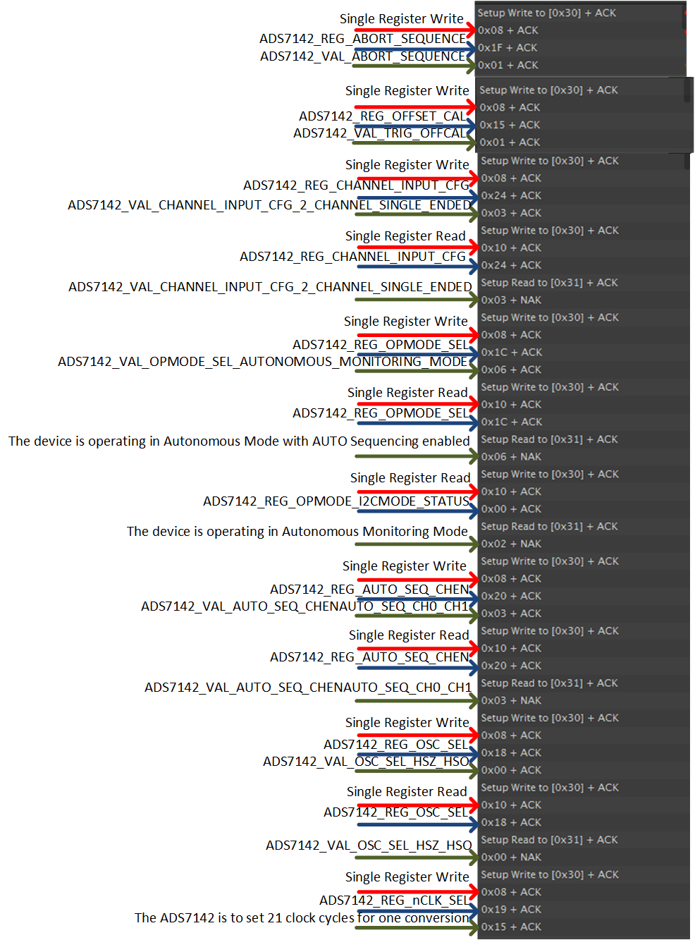
Figure 26 shows the channel configuration and selection of the opmode for this autonomous mode.
 Figure 26. Autonomous Mode Start Burst Dual-Channel Sampling Test Data 1
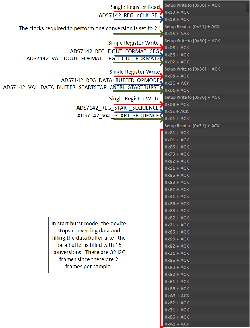
 Figure 27 shows the contents of the data buffer when filled.
 Figure 27. Autonomous Mode Start Burst Dual-Channel Sampling Test Data 2
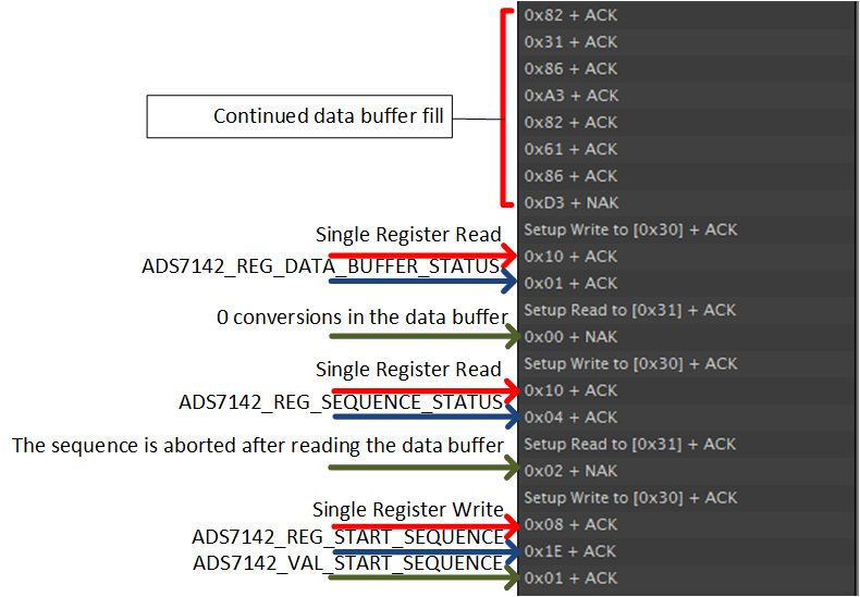
 After the data buffer contents are clocked out, there are no remaining conversions within the buffer. The conversion sequence must be restarted for the buffer to be filled again. Figure 28 shows this process.
 Figure 28. Autonomous Mode Start Burst Dual-Channel Sampling Test Data 3