SBAA288A July 2018 – January 2019 ADS7142
5.6 High Precision Mode
High precision mode increases the accuracy of the data measurement to 16-bit accuracy. In this mode, 16 12-bit conversions are placed into an accumulator that sums up the conversions in the accumulator. Equation 2 calculates the high precision data for each channel.

Each channel has an accumulator. Figure 33 shows the high precision mode conversion dynamics.
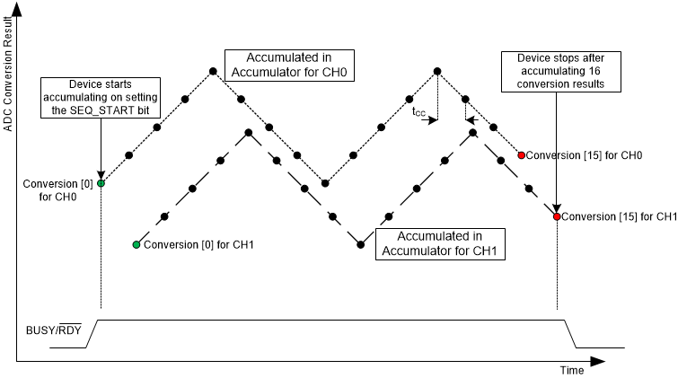 Figure 33. High Precision Mode With Dual-Channel Configurations
 The main routine is the following:
#include "ADS7142RegisterMap.h"

/*
ADS7142_HighPrecisionMode_AutoSequencing_CH0_CH1_Scan.c
*/

int
main(void)

{

//Initialize the master MCU (0 = 100 kHz SCL, 1 = 400 kHz SCL)
TM4C1294Init(0);

//Calibrate the offset out of ADS7142
ADS7142Calibrate();

//Let's put the ADS7142 into High Precision Mode with both channels enabled in Single-Ended Configuration
//Select the channel input configuration
ADS7142SingleRegisterWrite(ADS7142_REG_CHANNEL_INPUT_CFG, ADS7142_VAL_CHANNEL_INPUT_CFG_2_CHANNEL_SINGLE_ENDED);

//Confirm the input channel configuration
uint32_t channelconfig;
ADS7142SingleRegisterRead(ADS7142_REG_CHANNEL_INPUT_CFG, &channelconfig);

//Select the operation mode of the device
ADS7142SingleRegisterWrite(ADS7142_REG_OPMODE_SEL, ADS7142_VAL_OPMODE_SEL_HIGH_PRECISION_MODE);

//Confirm the operation mode selection
uint32_t opmodeselconfig;
ADS7142SingleRegisterRead(ADS7142_REG_OPMODE_SEL, &opmodeselconfig);

//Set the I2C Mode to High Speed (optional)
//ADS7142HighSpeedEnable(ADS7142_VAL_OPMODE_I2CMODE_HS_1);

//Check the I2C Mode Status
uint32_t opmodei2cconfig;
ADS7142SingleRegisterRead(ADS7142_REG_OPMODE_I2CMODE_STATUS, &opmodei2cconfig);

//Auto Sequence both channels 0 and 1
ADS7142SingleRegisterWrite(ADS7142_REG_AUTO_SEQ_CHEN, ADS7142_VAL_AUTO_SEQ_CHENAUTO_SEQ_CH0_CH1);

//Confirm Auto Sequencing is enabled
uint32_t autoseqchenconfig;
ADS7142SingleRegisterRead(ADS7142_REG_AUTO_SEQ_CHEN, &autoseqchenconfig);

//Select the Low Power Oscillator or high speed oscillator
ADS7142SingleRegisterWrite(ADS7142_REG_OSC_SEL, ADS7142_VAL_OSC_SEL_HSZ_HSO);

//Confirm the oscillator selection
uint32_t oscselconfig;
ADS7142SingleRegisterRead(ADS7142_REG_OSC_SEL, &oscselconfig);

//Set the minimum nCLK value for one conversion to maximize sampling speed
ADS7142SingleRegisterWrite(ADS7142_REG_nCLK_SEL, 21);

//Confirm the nCLK selection
uint32_t nCLKselconfig;
ADS7142SingleRegisterRead(ADS7142_REG_nCLK_SEL, &nCLKselconfig);

//Enable the accumulator
ADS7142SingleRegisterWrite(ADS7142_REG_ACC_EN, ADS7142_VAL_ACC_EN);

//Set SEQ_START Bit to start the sampling sequence
ADS7142SingleRegisterWrite(ADS7142_REG_START_SEQUENCE, ADS7142_VAL_START_SEQUENCE);

//Begin High Precision Mode Scanning Ch0 and Ch1 continuously

while(1)
{

//Sample 16 conversions from each channel
while (ADS7142DataRead_count(32) < 0);

//Check the Accumulator Status to count the number of conversions complete
uint32_t accstatus;
ADS7142SingleRegisterRead(ADS7142_REG_ACCUMULATOR_STATUS, &accstatus);

//Read the MSB of Ch0 Accumulated Data after 16 accumulations are complete
uint32_t accch0MSB;
ADS7142SingleRegisterRead(ADS7142_REG_ACC_CH0_MSB, &accch0MSB);

//Read the LSB of Ch0 Accumulated Data after 16 accumulations are complete
uint32_t accch0LSB;
ADS7142SingleRegisterRead(ADS7142_REG_ACC_CH0_LSB, &accch0LSB);

//Read the MSB of Ch1 Accumulated Data after 16 accumulations are complete
uint32_t accch1MSB;
ADS7142SingleRegisterRead(ADS7142_REG_ACC_CH1_MSB, &accch1MSB);

//Read the LSB of Ch1 Accumulated Data after 16 accumulations are complete
uint32_t accch1LSB;
ADS7142SingleRegisterRead(ADS7142_REG_ACC_CH1_LSB, &accch1LSB);

//Set the SEQ_START Bit again
ADS7142SingleRegisterWrite(ADS7142_REG_START_SEQUENCE, ADS7142_VAL_START_SEQUENCE);

}

//Return no errors
return 0;

}
Figure 34 shows the channel configuration and the selection of the opmode and oscillator for this ADS7142 functional mode.
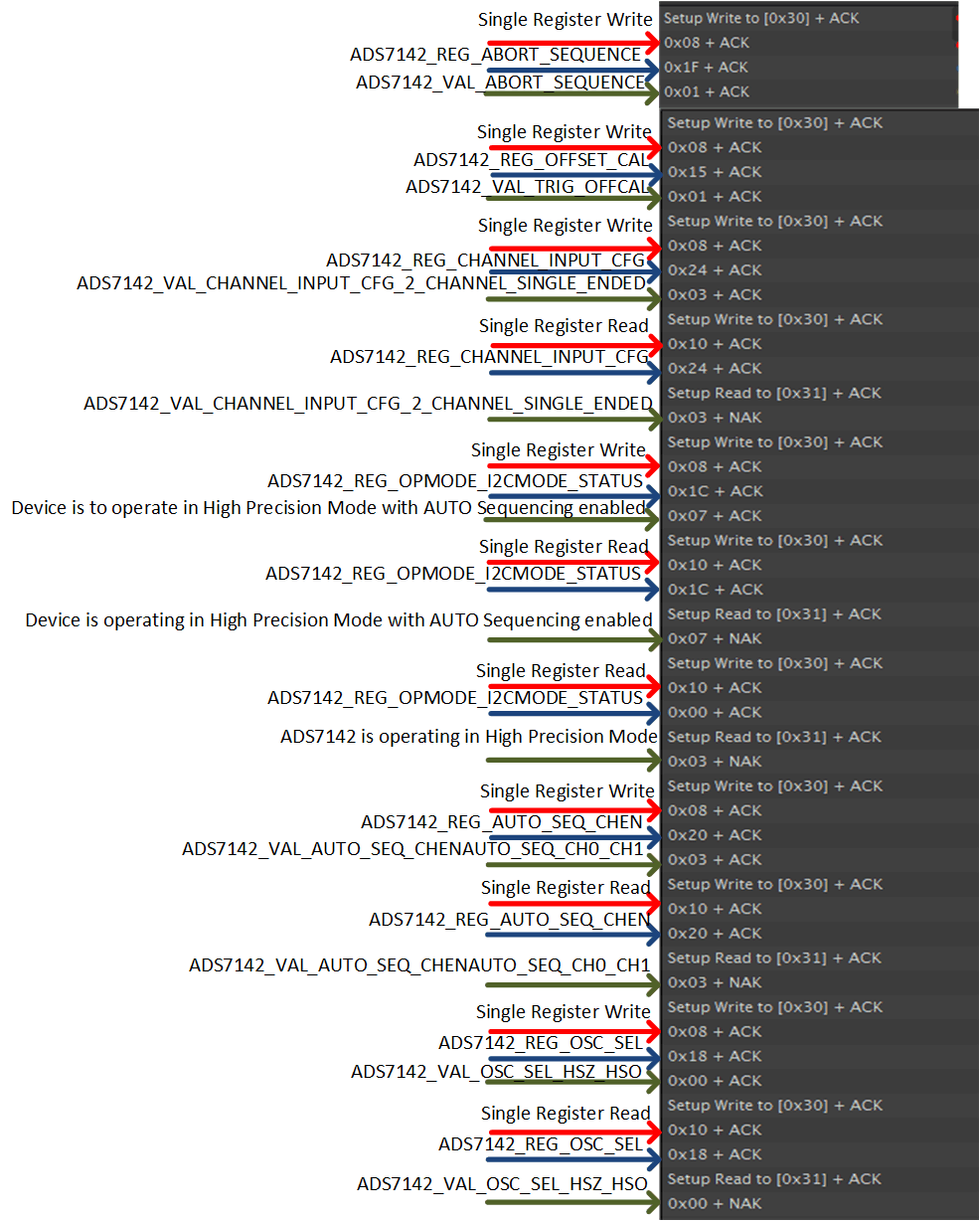 Figure 34. High Precision Mode Dual-Channel Sampling Test Data 1
 Figure 35 shows the setting of clock cycles required for a conversion, the enabling of accumulators, and the start of the conversion sequence.
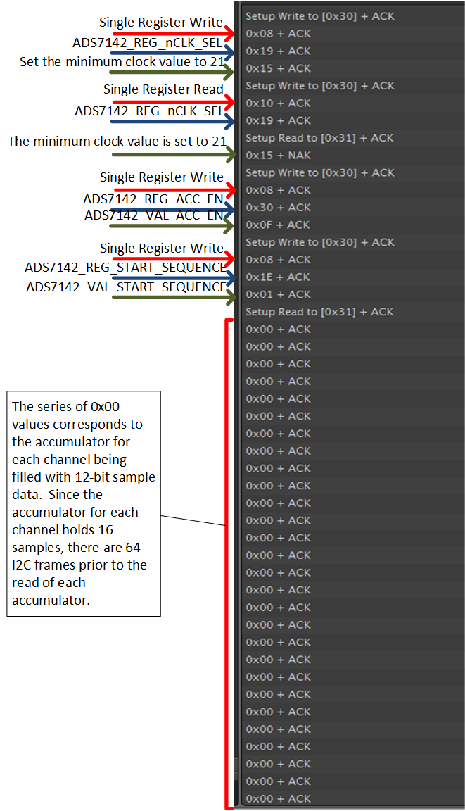 Figure 35. High Precision Mode Dual-Channel Sampling Test Data 2
 Figure 36 shows the number of conversions that fill the accumulator and the results of the high precision accumulation.
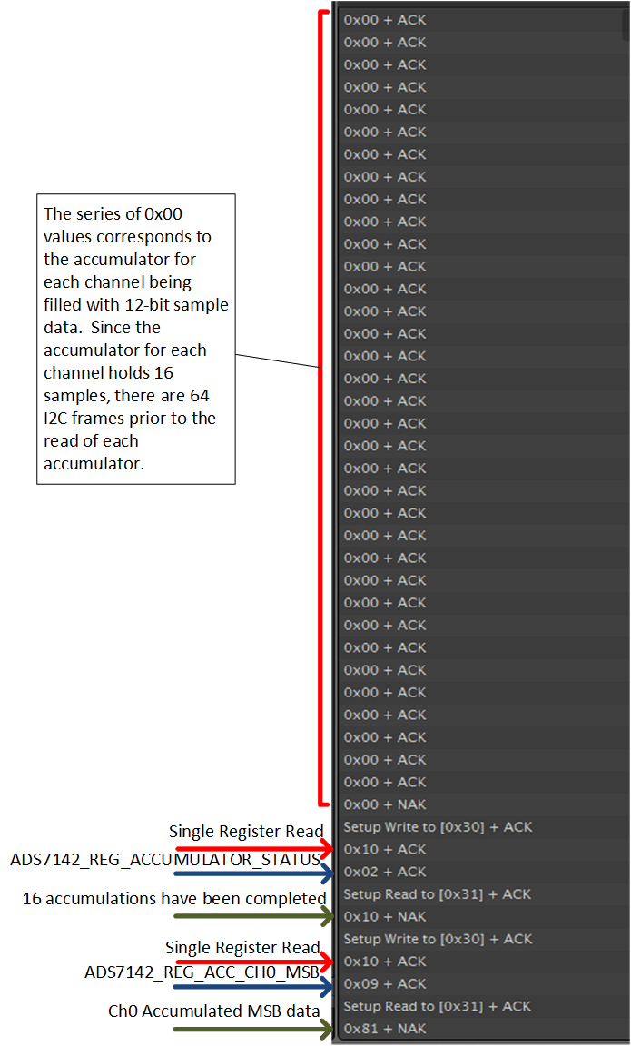 Figure 36. High Precision Mode Dual-Channel Sampling Test Data 3
 Figure 37 shows the accumulated results and restart of the conversion sequence.
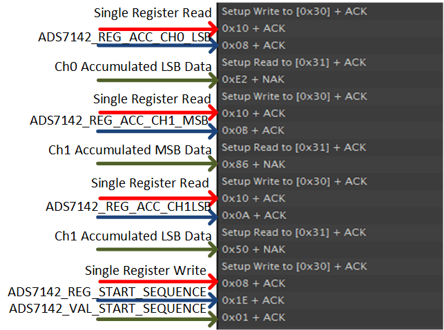 Figure 37. High Precision Mode Dual-Channel Sampling Test Data 4