ZHCSAW2E February 2013 – December 2014 UCC28251
PRODUCTION DATA.
- 1 特性
- 2 应用
- 3 说明
- 4 修订历史记录
- 5 说明 (续)
- 6 Pin Configuration and Functions
- 7 Specifications
-
8 Detailed Description
- 8.1 Overview
- 8.2 Functional Block Diagram
- 8.3
Feature Description
- 8.3.1 VDD (5/12)
- 8.3.2 VREF (Reference Generator) (20/7)
- 8.3.3 EN (Enable Pin) (18/5)
- 8.3.4 RT (Oscillator Frequency Set and Synchronization) (15/2)
- 8.3.5 SP (Synchronous Rectifier Turn-Off to Primary Output Turn-On Dead Time Programming) (13/19)
- 8.3.6 PS (Primary Output Turn-Off to Synchronous Rectifier Turn-On Dead Time Programming) (11/18)
- 8.3.7 RAMP/CS (PWM Ramp Input or Current Sense Input) (16/3)
- 8.3.8 REF/EA+ (1/8)
- 8.3.9 FB/EA- (2/9)
- 8.3.10 COMP (3/10)
- 8.3.11 VSENSE (14/1)
- 8.3.12 SS (Soft Start Programming Pin) (13/20)
- 8.3.13 ILIM (Current Limit for Cycle-by-Cycle Over-Current Protection) (17/4)
- 8.3.14 HICC (10/17)
- 8.3.15 OVP/OTP (19/6)
- 8.3.16 OUTA (9/16) and OUTB (8/15)
- 8.3.17 SRA (7/14) and SRB (6/13)
- 8.3.18 GND (4/11)
- 8.4 Device Functional Modes
-
9 Application and Implementation
- 9.1 Application Information
- 9.2
Typical Applications
- 9.2.1
Circuit Diagram in Design Example
- 9.2.1.1 Design Requirements
- 9.2.1.2
Detailed Design Procedure
- 9.2.1.2.1 Step 1: Power Stage Design
- 9.2.1.2.2 Step 2: Feedback Loop Design
- 9.2.1.2.3 Step 3: Programming The Device
- 9.2.1.2.4 Step 3-3: Determine Soft-Start Capacitance
- 9.2.1.2.5 Step 3-4: Determine Dead-Time Resistance
- 9.2.1.2.6 Step 3-5: Determine OCP Hiccup Off-Time Capacitance
- 9.2.1.2.7 Step 3-6: Determine Primary-Side OVP Resistance
- 9.2.1.2.8 Step 3-7: Select Capacitance for VDD and VREF
- 9.2.1.3 Application Curves
- 9.2.2 Secondary-Side Half-Bridge Controller With Synchronous Rectification
- 9.2.1
Circuit Diagram in Design Example
- 10Power Supply Recommendations
- 11Layout
- 12器件和文档支持
- 13机械、封装和可订购信息
封装选项
机械数据 (封装 | 引脚)
散热焊盘机械数据 (封装 | 引脚)
- RGP|20
订购信息
1 特性
2 应用
- 半桥、全桥、交错正激和推挽隔离式转换器
- 电信和数据通信电源
- 无线基站电源
- 服务器电源
- 工业电源系统
3 说明
UCC28251 PWM 控制器专为对预偏置启动要求严格的高功率密度 应用 而设计。UCC28251 的集成型同步整流器控制输出针对高效和高性能拓扑结构,诸如半桥、全桥、交错正激和推挽结构。与 UCC28251 一同使用的 UCC27210 半桥驱动器和 UCC2752x MOSFET 驱动器提供一个完整的电源转换器解决方案。
UCC28251 是 UCC28250 PWM 控制器的功能性变体。UCC28251 在很大程度上保留了 UCC28250 的基本功能,同时经过设计增强了在离线式 400V 输入 DC-DC 应用 和 48V 输入全桥或半桥 应用中的性能。
器件信息(1)
| 器件型号 | 封装 | 封装尺寸(标称值) |
|---|---|---|
| UCC28251 | 薄型小外形尺寸封装 (TSSOP) (20) | 6.50mm x 4.40mm |
| VQFN (20) | 4.00mm x 4.00mm |
- 如需了解所有可用封装,请见数据表末尾的可订购产品附录。
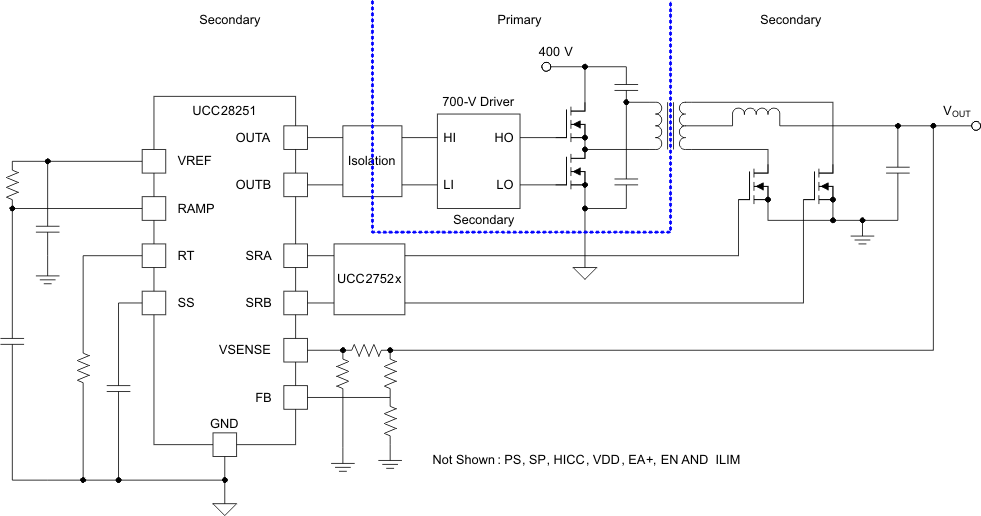
简单应用图(400V输入DC 至 DC 转换器)

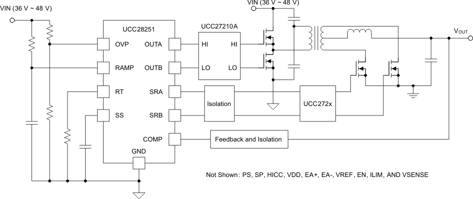
简单应用图(48V输入DC 至 DC 转换器)
