ZHCSFP2B October   2016  – September 2021 TPS3850

PRODUCTION DATA  

  1. 特性
  2. 应用
  3. 说明
  4. Revision History
  5. Pin Configuration and Functions
  6. Specifications
    1. 6.1 Absolute Maximum Ratings
    2. 6.2 ESD Ratings
    3. 6.3 Recommended Operating Conditions
    4. 6.4 Thermal Information
    5. 6.5 Electrical Characteristics
    6. 6.6 Timing Requirements
    7. 6.7 Timing Diagrams
    8. 6.8 Typical Characteristics
  7. Detailed Description
    1. 7.1 Overview
    2. 7.2 Functional Block Diagrams
    3. 7.3 Feature Description
      1. 7.3.1 CRST
      2. 7.3.2 RESET
      3. 7.3.3 Over- and Undervoltage Fault Detection
      4. 7.3.4 Adjustable Operation Using the TPS3850H01
      5. 7.3.5 Window Watchdog
        1. 7.3.5.1 SET0 and SET1
          1. 7.3.5.1.1 Enabling the Window Watchdog
          2. 7.3.5.1.2 Disabling the Watchdog Timer When Using the CRST Capacitor
          3. 7.3.5.1.3 SET0 and SET1 During Normal Watchdog Operation
      6. 7.3.6 Window Watchdog Timer
        1. 7.3.6.1 CWD
        2. 7.3.6.2 WDI Functionality
        3. 7.3.6.3 WDO Functionality
    4. 7.4 Device Functional Modes
      1. 7.4.1 VDD is Below VPOR ( VDD < VPOR)
      2. 7.4.2 Above Power-On-Reset But Less Than UVLO (VPOR ≤ VDD < VUVLO)
      3. 7.4.3 Above UVLO But Less Than VDD (min) (VUVLO ≤ VDD < VDD (min))
      4. 7.4.4 Normal Operation (VDD ≥ VDD (min))
  8. Application and Implementation
    1. 8.1 Application Information
      1. 8.1.1 CRST Delay
        1. 8.1.1.1 Factory-Programmed Reset Delay Timing
        2. 8.1.1.2 Programmable Reset Delay-Timing
      2. 8.1.2 CWD Functionality
        1. 8.1.2.1 Factory-Programmed Timing Options
        2. 8.1.2.2 Adjustable Capacitor Timing
      3. 8.1.3 Adjustable SENSE Configuration
      4. 8.1.4 Overdrive on the SENSE Pin
    2. 8.2 Typical Applications
      1. 8.2.1 Design 1: Monitoring a 1.2-V Rail with Factory-Programmable Watchdog Timing
        1. 8.2.1.1 Design Requirements
        2. 8.2.1.2 Detailed Design Procedure
          1. 8.2.1.2.1 Monitoring the 1.2-V Rail
          2. 8.2.1.2.2 Meeting the Minimum Reset Delay
          3. 8.2.1.2.3 Setting the Watchdog Window
          4. 8.2.1.2.4 Calculating the RESET and WDO Pullup Resistor
        3. 8.2.1.3 Application Curves
      2. 8.2.2 Design 2: Using TPS3850H01 to monitor a 0.7-V Rail With an Adjustable Window Watchdog Timing
        1. 8.2.2.1 Design Requirements
        2. 8.2.2.2 Detailed Design Procedure
          1. 8.2.2.2.1 Meeting the Minimum Reset Delay
          2. 8.2.2.2.2 Setting the Window Watchdog
          3. 8.2.2.2.3 Watchdog Disabled During the Initialization Period
          4. 8.2.2.2.4 Calculating the Sense Resistor
        3. 8.2.2.3 Application Curves
  9. Power Supply Recommendations
  10. 10Layout
    1. 10.1 Layout Guidelines
    2. 10.2 Layout Example
  11. 11Device and Documentation Support
    1. 11.1 Device Support
      1. 11.1.1 Device Nomenclature
    2. 11.2 Documentation Support
      1. 11.2.1 Related Documentation
    3. 11.3 接收文档更新通知
    4. 11.4 支持资源
    5. 11.5 Trademarks
    6. 11.6 Electrostatic Discharge Caution
    7. 11.7 术语表
  12. 12Mechanical, Packaging, and Orderable Information

封装选项

机械数据 (封装 | 引脚)
散热焊盘机械数据 (封装 | 引脚)
订购信息

Adjustable Operation Using the TPS3850H01

The adjustable version (TPS3850H01) can be used to monitor any voltage rail down to 0.4 V using the circuit illustrated in Figure 7-4. When using the TPS3850H01, the device does not function as a window comparator; instead, the device only monitors the undervoltage threshold. To monitor a user-defined voltage, the target threshold voltage for the monitored supply (VMON) and the resistor divider values can be calculated by using Equation 1 and Equation 2, respectively:

Equation 1. GUID-9466996C-E297-4221-ACB6-E205ECA87D4B-low.gif

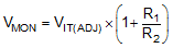
Equation 1 can be used to calculate either the negative threshold or the positive threshold by replacing VITx with either VITN or VITN + VHYST, respectively.

Equation 2. RTOTAL = R1 + R2

Large resistor values minimize current consumption; however, the input bias current of the device degrades accuracy if the current through the resistors is too low. Therefore, choosing an RTOTAL value so that the current through the resistor divider is at least 100 times larger than the maximum SENSE pin current (ISENSE) ensures a good degree of accuracy; see the IQ vs Accuracy Tradeoff In Designing Resistor Divider Input To A Voltage Supervisor (SLVA450) application report for more details on sizing input resistors.

GUID-FAA848A4-A114-42CB-A93A-7306BA280E54-low.gifFigure 7-4 Adjustable Voltage Monitor