ZHCSIW7B October   2018  – January 2020 TPS25982

PRODUCTION DATA.  

  1. 特性
  2. 应用
  3. 说明
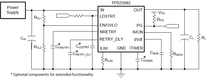
    1.     简化电路原理图
  4. 修订历史记录
  5. 器件比较表
  6. Pin Configuration and Functions
    1.     Pin Functions
  7. Specifications
    1. 7.1 Absolute Maximum Ratings
    2. 7.2 ESD Ratings
    3. 7.3 Recommended Operating Conditions
    4. 7.4 Thermal Information
    5. 7.5 Electrical Characteristics
    6. 7.6 Timing Requirements
    7. 7.7 Switching Characteristics
    8. 7.8 Typical Characteristics
  8. Detailed Description
    1. 8.1 Overview
    2. 8.2 Functional Block Diagram
    3. 8.3 Feature Description
      1. 8.3.1 Undervoltage Protection (UVLO and UVP)
      2. 8.3.2 Overvoltage Protection (OVP)
      3. 8.3.3 Inrush Current, Overcurrent, and Short-Circuit Protection
        1. 8.3.3.1 Slew Rate and Inrush Current Control (dVdt)
        2. 8.3.3.2 Circuit Breaker
        3. 8.3.3.3 Active Current Limiting
        4. 8.3.3.4 Short-Circuit Protection
      4. 8.3.4 Overtemperature Protection (OTP)
      5. 8.3.5 Analog Load Current Monitor (IMON)
      6. 8.3.6 Power Good (PG)
      7. 8.3.7 Load Detect/Handshake (LDSTRT)
    4. 8.4 Fault Response
    5. 8.5 Device Functional Modes
  9. Application and Implementation
    1. 9.1 Application Information
    2. 9.2 Typical Application: Standby Power Rail Protection in Datacenter Servers
      1. 9.2.1 Design Requirements
      2. 9.2.2 Detailed Design Procedure
        1. 9.2.2.1 Device Selection
        2. 9.2.2.2 Setting the Current Limit Threshold: RILIM Selection
        3. 9.2.2.3 Setting the Undervoltage Lockout Set Point
        4. 9.2.2.4 Choosing the Current Monitoring Resistor: RIMON
        5. 9.2.2.5 Setting the Output Voltage Ramp Time (TdVdt)
          1. 9.2.2.5.1 Case 1: Start-Up Without Load: Only Output Capacitance COUT Draws Current
          2. 9.2.2.5.2 Case 2: Start-Up With Load: Output Capacitance COUT and Load Draw Current
        6. 9.2.2.6 Setting the Load Handshake (LDSTRT) Delay
        7. 9.2.2.7 Setting the Transient Overcurrent Blanking Interval (tITIMER)
        8. 9.2.2.8 Setting the Auto-Retry Delay and Number of Retries
      3. 9.2.3 Application Curves
    3. 9.3 System Examples
      1. 9.3.1 Optical Module Power Rail Path Protection
        1. 9.3.1.1 Design Requirements
        2. 9.3.1.2 Device Selection
        3. 9.3.1.3 External Component Settings
        4. 9.3.1.4 Voltage Drop
        5. 9.3.1.5 Application Curves
      2. 9.3.2 Input Protection for 12-V Rail Applications: PCIe Cards, Storage Interfaces and DC Fans
  10. 10Power Supply Recommendations
    1. 10.1 Transient Protection
    2. 10.2 Output Short-Circuit Measurements
  11. 11Layout
    1. 11.1 Layout Guidelines
    2. 11.2 Layout Example
  12. 12器件和文档支持
    1. 12.1 文档支持
      1. 12.1.1 相关文档
        1. 12.1.1.1 相关链接
    2. 12.2 接收文档更新通知
    3. 12.3 社区资源
    4. 12.4 商标
    5. 12.5 静电放电警告
    6. 12.6 Glossary
  13. 13机械、封装和可订购信息

封装选项

机械数据 (封装 | 引脚)
散热焊盘机械数据 (封装 | 引脚)
订购信息

说明

TPS25982 系列电子保险丝是采用小型封装的高度集成电路保护和电源管理解决方案。这些器件可在宽输入电压范围内工作。单个器件适用于需要最小 I*R 压降的低电压系统以及需要低功率耗散的高电压、高电流系统。它们能够非常有效地抵御过载、短路、电压浪涌和过多浪涌电流。

过压事件受内部截止电路的限制,可通过多个器件选项来选择过压阈值。

存在多种器件选项,可在过流情况响应、断路器或有源限流器之间进行选择。可以使用单个外部电阻器来设置过流限值和快速跳变(短路)阈值。这些器件通过区分瞬态事件和实际故障来智能地管理过流响应,从而允许系统在线路和负载瞬变期间不间断运行,而不会影响故障保护的稳健性。可将该器件配置为在故障关闭后保持闭锁或自动重试。可使用电容器来配置自动重试次数和重试延迟。这使远程系统能够自动从临时故障中恢复,同时确保电源不会因持续的故障而无限期地承受应力。

TPS25982 器件采用 4mm × 4mm 小型 QFN 封装。这些器件的额定工作结温范围为 –40˚C 至 125˚C。

器件信息(1)

器件型号 封装 封装尺寸(标称值)
TPS25982 QFN (24) 4.0mm × 4.0mm
  1. 如需了解所有可用封装,请参阅数据表末尾的可订购产品附录。

简化电路原理图

TPS25982 Simplified-schematics-Page-1.gif