ZHCSCN4F January 2014 – July 2017 TPS22968
PRODUCTION DATA.
- 1 特性
- 2 应用
- 3 说明
- 4 修订历史记录
- 5 Device Comparison
- 6 Pin Configuration and Functions
- 7 Specifications
- 8 Parameter Measurement Information
- 9 Detailed Description
- 10Application and Implementation
- 11Power Supply Recommendations
- 12Layout
- 13器件和文档支持
- 14机械、封装和可订购信息
7 Specifications
7.1 Absolute Maximum Ratings
Over operating free-air temperature (unless otherwise noted)(1)| MIN | MAX | UNIT (2) | |||
|---|---|---|---|---|---|
| VIN1,2 | Input voltage | –0.3 | 6 | V | |
| VBIAS | Bias voltage | –0.3 | 6 | V | |
| VOUT1,2 | Output voltage | –0.3 | 6 | V | |
| VON1,2 | ON voltage | –0.3 | 6 | V | |
| IMAX | Maximum continuous switch current per channel, TA = 30 °C | 4 | A | ||
| IPLS | Maximum pulsed switch current, pulse < 300 µs, 2% duty cycle | 6 | A | ||
| TJ | Maximum junction temperature | 125 | °C | ||
| Tstg | Storage temperature | –65 | 150 | °C | |
(1) Stresses beyond those listed under Absolute Maximum Ratings may cause permanent damage to the device. These are stress ratings only, which do not imply functional operation of the device at these or any other conditions beyond those indicated under Recommended Operating Conditions. Exposure to absolute-maximum-rated conditions for extended periods may affect device reliability.
(2) All voltage values are with respect to network ground terminal.
7.2 ESD Ratings
| VALUE | UNIT | |||
|---|---|---|---|---|
| V(ESD) | Electrostatic discharge | Human-body model (HBM), per ANSI/ESDA/JEDEC JS-001 (1) | ±2000 | V |
| Charged-device model (CDM), per JEDEC specification JESD22-C101 (2) | ±1000 | |||
(1) JEDEC document JEP155 states that 500-V HBM allows safe manufacturing with a standard ESD control process. Manufacturing with less than 500-V HBM is possible with the necessary precautions.
(2) JEDEC document JEP157 states that 250-V CDM allows safe manufacturing with a standard ESD control process. Manufacturing with less than 250-V CDM is possible with the necessary precautions.
7.3 Recommended Operating Conditions
| MIN | MAX | UNIT | |||
|---|---|---|---|---|---|
| VIN1,2 | Input voltage | 0.8 | VBIAS | V | |
| VBIAS | Bias voltage | 2.5 | 5.5 | V | |
| VON1,2 | ON voltage | 0 | 5.5 | V | |
| VOUT1,2 | Output voltage | VIN | V | ||
| VIH, ON1,2 | High-level input voltage, ON1,2 | VBIAS = 2.5 V to 5.5 V | 1.2 | 5.5 | V |
| VIL, ON1,2 | Low-level input voltage, ON1,2 | VBIAS = 2.5 V to 5.5 V | 0 | 0.5 | V |
| CIN1,2 | Input capacitor | 1(1) | µF | ||
| TA | Operating free-air temperature (2) | –40 | 105 | °C | |
(1) See the Application Information section.
(2) In applications where high power dissipation and/or poor package thermal resistance is present, the maximum ambient temperature may have to be derated. Maximum ambient temperature [TA(max)] is dependent on the maximum operating junction temperature [TJ(max)], the maximum power dissipation of the device in the application [PD(max)], and the junction-to-ambient thermal resistance of the part/package in the application (RθJA), as given by the following equation: TA(max) = TJ(max) – (RθJA × PD(max)).
7.4 Thermal Information
| THERMAL METRIC (1) (2) | TPS22968 | UNIT | |
|---|---|---|---|
| DPU (WSON) | |||
| 14 PINS | |||
| RθJA | Junction-to-ambient thermal resistance | 62.5 | °C/W |
| RθJC(top) | Junction-to-case (top) thermal resistance | 70.2 | °C/W |
| RθJB | Junction-to-board thermal resistance | 23.2 | °C/W |
| ψJT | Junction-to-top characterization parameter | 2.5 | °C/W |
| ψJB | Junction-to-board characterization parameter | 23.2 | °C/W |
| RθJC(bot) | Junction-to-case (bottom) thermal resistance | 9 | °C/W |
(1) For more information about traditional and new thermal metrics, see the Semiconductor and IC Package Thermal Metrics application report.
(2) For thermal estimates of this device based on PCB copper area, see the TI PCB Thermal Calculator.
7.5 Electrical Characteristics (VBIAS = 5 V)
Unless otherwise noted, the specification in the following table applies over the operating ambient temperature–40°C ≤ TA ≤ +105°C (full) and VBIAS = 5 V. Typical values are for TA = 25°C (unless otherwise noted).
| PARAMETER | TEST CONDITIONS | TA | MIN | TYP | MAX | UNIT | ||
|---|---|---|---|---|---|---|---|---|
| POWER SUPPLIES AND CURRENTS | ||||||||
| IQ, VBIAS | VBIAS quiescent current (both channels) | IOUT1 = IOUT2 = 0, VIN1,2 = VON1,2 = VBIAS = 5 V | –40°C to +105°C | 55 | 70 | µA | ||
| VBIAS quiescent current (single channel) | IOUT1 = IOUT2 = 0, VON2 = 0 V, VIN1,2 = VON1 = VBIAS = 5 V | –40°C to +105°C | 55 | 68 | µA | |||
| ISD, VBIAS | VBIAS shutdown current | VON1,2 = 0 V, VOUT1,2 = 0 V | –40°C to +105°C | 1 | 2 | µA | ||
| ISD, VIN1,2 | VIN1,2 shutdown current (per channel) | VON1,2 = 0 V, VOUT1,2 = 0 V | VIN1,2 = 5 V | –40°C to +85°C | 0.5 | 8 | µA | |
| –40°C to +105°C | 10 | |||||||
| VIN1,2 = 3.3 V | –40°C to +85°C | 0.1 | 3 | |||||
| –40°C to +105°C | 4 | |||||||
| VIN1,2 = 1.8 V | –40°C to +85°C | 0.07 | 2 | |||||
| –40°C to +105°C | 3 | |||||||
| VIN1,2 = 1.2 V | –40°C to +85°C | 0.05 | 1 | |||||
| –40°C to +105°C | 2 | |||||||
| VIN1,2 = 0.8 V | –40°C to +85°C | 0.04 | 1 | |||||
| –40°C to +105°C | 2 | |||||||
| ION1,2 | ON pin input leakage current | VON = 5.5 V | –40°C to +105°C | 0.1 | µA | |||
| RESISTANCE CHARACTERISTICS | ||||||||
| RON | On-state resistance | IOUT = –200 mA, VBIAS = 5 V VON1,2 = 5 V |
VIN = 5 V | 25°C | 27 | 36 | mΩ | |
| –40°C to +85°C | 40 | |||||||
| –40°C to +105°C | 42 | |||||||
| VIN = 3.3 V | 25°C | 25 | 34 | mΩ | ||||
| –40°C to +85°C | 38 | |||||||
| –40°C to +105°C | 40 | |||||||
| VIN = 1.8 V | 25°C | 25 | 34 | mΩ | ||||
| –40°C to +85°C | 38 | |||||||
| –40°C to +105°C | 40 | |||||||
| VIN = 1.5 V | 25°C | 25 | 34 | mΩ | ||||
| –40°C to +85°C | 38 | |||||||
| –40°C to +105°C | 40 | |||||||
| VIN = 1.2 V | 25°C | 25 | 34 | mΩ | ||||
| –40°C to +85°C | 38 | |||||||
| –40°C to +105°C | 40 | |||||||
| VIN = 0.8 V | 25°C | 25 | 34 | mΩ | ||||
| –40°C to +85°C | 38 | |||||||
| –40°C to +105°C | 40 | |||||||
| RPD (1) | Output pulldown resistance | VIN = 5 V, VON = 0 V, IOUT = 10 mA | –40°C to +105°C | 270 | 320 | Ω | ||
(1) TPS22968 only.
7.6 Electrical Characteristics (VBIAS = 2.5 V)
Unless otherwise noted, the specification in the following table applies over the operating ambient temperature–40 °C ≤ TA ≤ +105 °C (full) and VBIAS = 2.5 V. Typical values are for TA = 25°C (unless otherwise noted).
| PARAMETER | TEST CONDITIONS | TA | MIN | TYP | MAX | UNIT | ||
|---|---|---|---|---|---|---|---|---|
| POWER SUPPLIES AND CURRENTS | ||||||||
| IQ, VBIAS | VBIAS quiescent current (both channels) | IOUT1 = IOUT2 = 0, VIN1,2 = VON1,2 = VBIAS = 2.5 V | –40°C to +105°C | 18 | 27 | µA | ||
| VBIAS quiescent current (single channel) | IOUT1 = IOUT2 = 0, VON2 = 0 V, VIN1,2 = VON1 = VBIAS = 2.5 V | –40°C to +105°C | 18 | 27 | µA | |||
| ISD, VBIAS | VBIAS shutdown current | VON1,2 = 0 V, VOUT1,2 = 0 V | –40°C to +105°C | 0.5 | 2 | µA | ||
| ISD, VIN1,2 | VIN1,2 shutdown current (per channel) | VON1,2 = 0 V, VOUT1,2 = 0 V | VIN1,2 = 2.5 V | –40°C to +85°C | 0.1 | 2 | µA | |
| –40°C to +105°C | 4 | |||||||
| VIN1,2 = 1.8 V | –40°C to +85°C | 0.07 | 2 | |||||
| –40°C to +105°C | 3 | |||||||
| VIN1,2 = 1.2 V | –40°C to +85°C | 0.05 | 1 | |||||
| –40°C to +105°C | 2 | |||||||
| VIN1,2 = 0.8 V | –40°C to +85°C | 0.04 | 1 | |||||
| –40°C to +105°C | 2 | |||||||
| ION1,2 | ON pin input leakage current | VON = 5.5 V | –40°C to +85°C | 0.1 | µA | |||
| RESISTANCE CHARACTERISTICS | ||||||||
| RON | On-state resistance | IOUT = –200 mA, VBIAS = 2.5 V VON1,2 = 5 V |
VIN = 2.5 V | 25°C | 30 | 39 | mΩ | |
| –40°C to +85°C | 44 | |||||||
| –40°C to +105°C | 46 | |||||||
| VIN = 1.8 V | 25°C | 28 | 36 | mΩ | ||||
| –40°C to +85°C | 41 | |||||||
| –40°C to +105°C | 43 | |||||||
| VIN = 1.5 V | 25°C | 28 | 36 | mΩ | ||||
| –40°C to +85°C | 41 | |||||||
| –40°C to +105°C | 43 | |||||||
| VIN = 1.2 V | 25°C | 27 | 36 | mΩ | ||||
| –40°C to +85°C | 41 | |||||||
| –40°C to +105°C | 43 | |||||||
| VIN = 0.8 V | 25°C | 26 | 35 | mΩ | ||||
| –40°C to +85°C | 39 | |||||||
| –40°C to +105°C | 41 | |||||||
| RPD (1) | Output pulldown resistance | VIN = 2.5 V, VON = 0 V, IOUT = 10 mA | –40°C to +105°C | 270 | 320 | Ω | ||
(1) TPS22968 only.
7.7 Switching Characteristics
| PARAMETER | TEST CONDITION | MIN | TYP | MAX | UNIT | |
|---|---|---|---|---|---|---|
| VIN = VON = VBIAS = 5 V, TA = 25 °C (unless otherwise noted) | ||||||
| tON | Turnon time | RL = 10 Ω, CL = 0.1 µF, CT = 1000 pF | 1128 | µs | ||
| tOFF | Turnoff time | RL = 10 Ω, CL = 0.1 µF, CT = 1000 pF | 5 | |||
| tR | VOUT rise time | RL = 10 Ω, CL = 0.1 µF, CT = 1000 pF | 1387 | |||
| tF | VOUT fall time | RL = 10 Ω, CL = 0.1 µF, CT = 1000 pF | 2 | |||
| tD | ON delay time | RL = 10 Ω, CL = 0.1 µF, CT = 1000 pF | 455 | |||
| VIN = 0.8 V, VON = VBIAS = 5 V, TA = 25 ºC (unless otherwise noted) | ||||||
| tON | Turnon time | RL = 10 Ω, CL = 0.1 µF, CT = 1000 pF | 508 | µs | ||
| tOFF | Turnoff time | RL = 10 Ω, CL = 0.1 µF, CT = 1000 pF | 33 | |||
| tR | VOUT rise time | RL = 10 Ω, CL = 0.1 µF, CT = 1000 pF | 273 | |||
| tF | VOUT fall time | RL = 10 Ω, CL = 0.1 µF, CT = 1000 pF | 2 | |||
| tD | ON delay time | RL = 10 Ω, CL = 0.1 µF, CT = 1000 pF | 377 | |||
| VIN = 2.5 V, VON = 5 V, VBIAS = 2.5V, TA = 25 ºC (unless otherwise noted) | ||||||
| tON | Turnon time | RL = 10 Ω, CL = 0.1 µF, CT = 1000 pF | 1718 | µs | ||
| tOFF | Turnoff time | RL = 10 Ω, CL = 0.1 µF, CT = 1000 pF | 7 | |||
| tR | VOUT rise time | RL = 10 Ω, CL = 0.1 µF, CT = 1000 pF | 1701 | |||
| tF | VOUT fall time | RL = 10 Ω, CL = 0.1 µF, CT = 1000 pF | 2 | |||
| tD | ON delay time | RL = 10 Ω, CL = 0.1 µF, CT = 1000 pF | 859 | |||
| VIN = 0.8 V, VON = 5 V, VBIAS = 2.5 V, TA = 25 ºC (unless otherwise noted) | ||||||
| tON | Turnon time | RL = 10 Ω, CL = 0.1 µF, CT = 1000 pF | 1117 | µs | ||
| tOFF | Turnoff time | RL = 10 Ω, CL = 0.1 µF, CT = 1000 pF | 30 | |||
| tR | VOUT rise time | RL = 10 Ω, CL = 0.1 µF, CT = 1000 pF | 651 | |||
| tF | VOUT fall time | RL = 10 Ω, CL = 0.1 µF, CT = 1000 pF | 2 | |||
| tD | ON delay time | RL = 10 Ω, CL = 0.1 µF, CT = 1000 pF | 775 | |||
7.8 Typical DC Characteristics
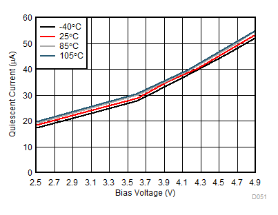
| VIN1 = VIN2 = VBIAS | VOUT = Open | |
| VON1 = VON2 = 5 V |
(Both Channels)
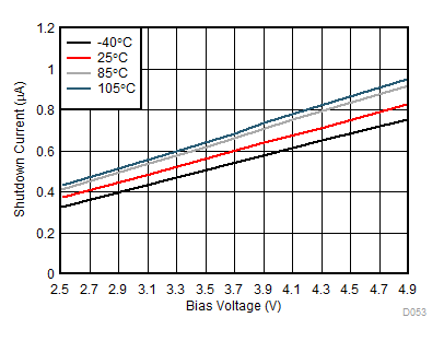
| VIN1 = VIN2 = VBIAS | VOUT = 0 V | |
| VON1 = VON2 = 0 V |
(Both Channels)
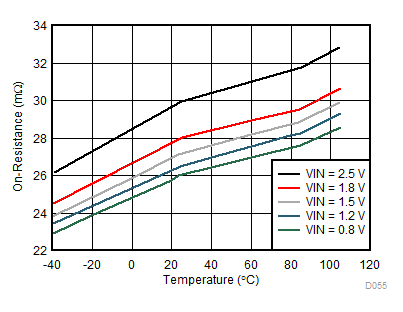
| VBIAS = 2.5 V | ||
| IOUT = –200 mA |
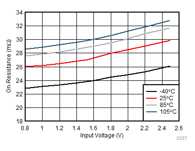
| VBIAS = 2.5 V | ||
| I OUT = –200 mA |
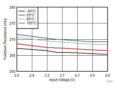
| VBIAS = 5 V | IOUT = 1 mA | |
| VON = 0 V |
(Single Channel)
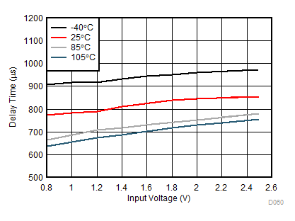
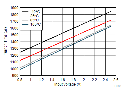
| VBIAS = 2.5 V | ||
| CT= 1 nF |
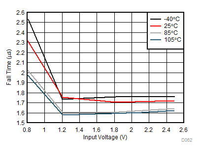
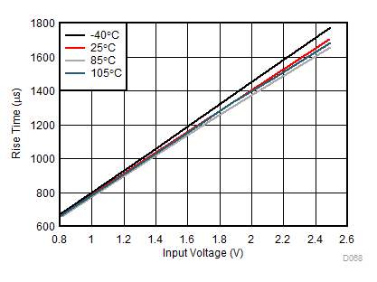
| VBIAS = 2.5 V | ||
| CT = 1 nF |
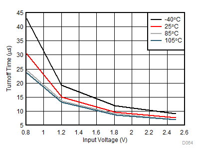
| VBIAS = 2.5 V | ||
| CT = 1 nF |
| VBIAS = 2.5 V | ||
| CT = 1 nF |
| VBIAS = 2.5 V | ||
| CT = 1 nF |
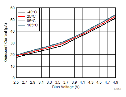
| VIN1 = VIN2 = VBIAS | VON2 = 0 V | |
| VON1 = 5 V | VOUT = Open |
(Single Channel)
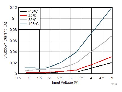
| VBIAS = 5 V | VOUT = 0 V | |
| VON1 = VON2 = 0 V |
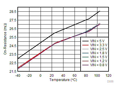
| VBIAS = 5 V | ||
| IOUT = –200 mA |
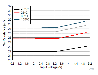
| VBIAS = 5 V | ||
| IOUT = –200 mA |
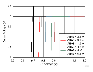
| TA = 25°C | ||
| VIN = 2 V |
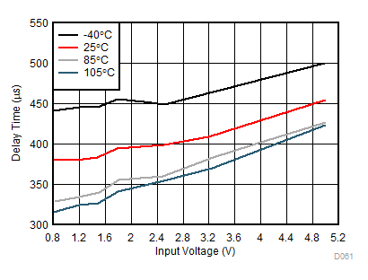
| VBIAS = 5 V | ||
| CT = 1 nF |
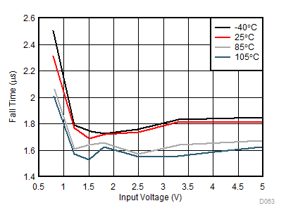
| VBIAS = 5 V | ||
| CT = 1 nF |
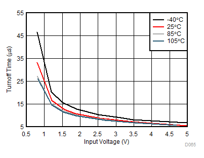
| VBIAS = 5 V | ||
| CT = 1 nF |
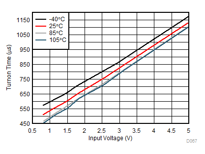
| VBIAS = 5 V | ||
| CT = 1 nF |
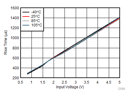
| VBIAS = 5 V | ||
| CT = 1 nF |
7.9 Typical AC Characteristics
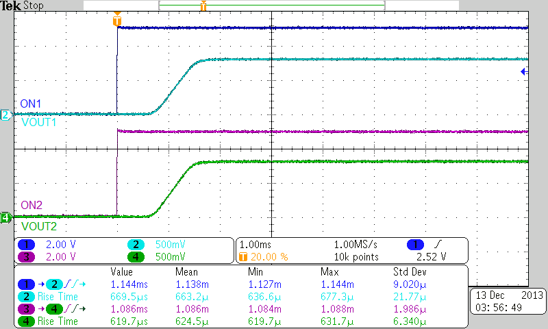
| VIN = 0.8 V | VBIAS = 2.5 V | CIN = 1 µF |
| RL = 10 Ω | CL = 0.1 µF |
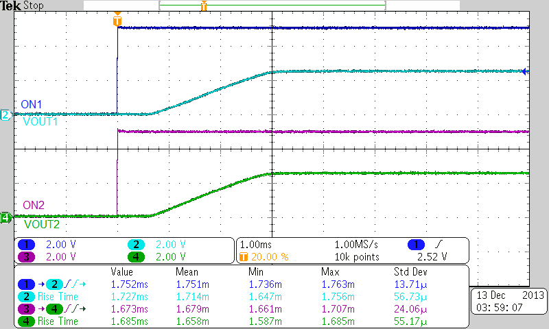
| VIN = 2.5 V | VBIAS = 2.5 V | CIN = 1 µF |
| RL = 10 Ω | CL = 0.1 µF |
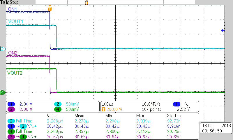
| VIN = 0.8 V | VBIAS = 2.5 V | CIN = 1 µF |
| RL = 10 Ω | CL = 0.1 µF |
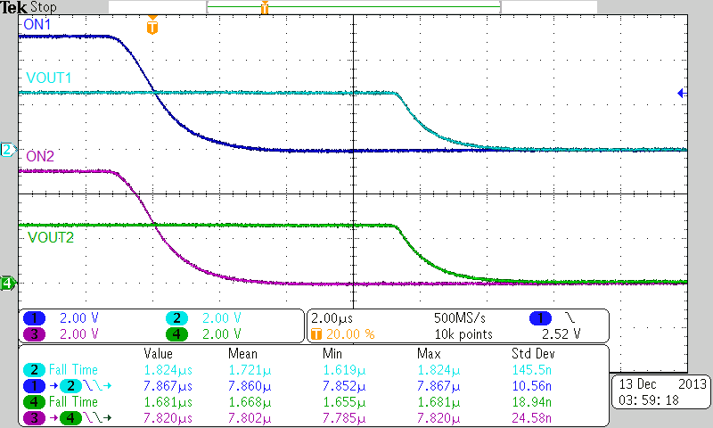
| VIN = 2.5 V | VBIAS = 2.5 V | CIN = 1 µF |
| RL = 10 Ω | CL = 0.1 µF |
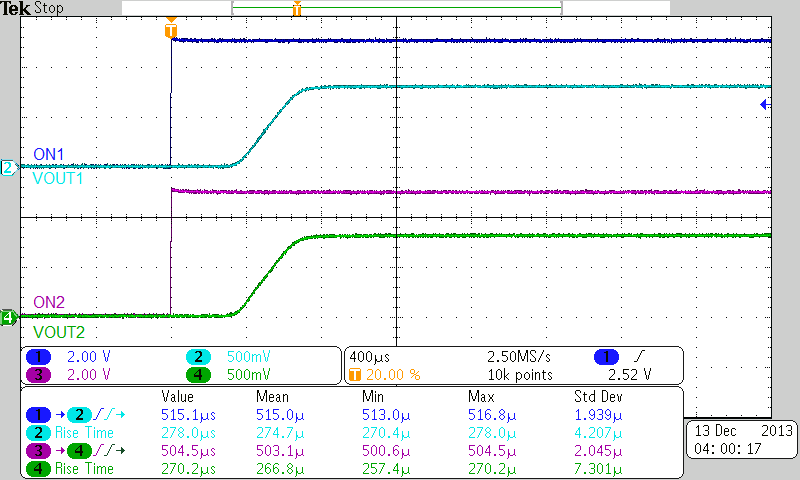
| VIN = 0.8 V | VBIAS = 5 V | CIN = 1 µF |
| RL = 10 Ω | CL = 0.1 µF |
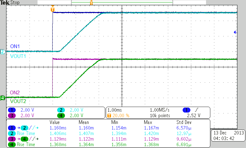
| VIN = 5 V | VBIAS = 5 V | CIN = 1 µF |
| RL = 10 Ω | CL = 0.1 µF |
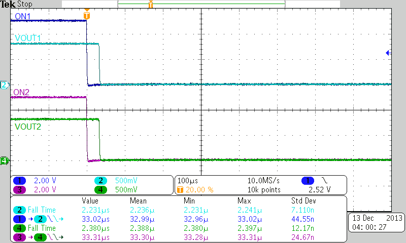
| VIN = 0.8 V | VBIAS = 5 V | CIN = 1 µF |
| RL = 10 Ω | CL = 0.1 µF |
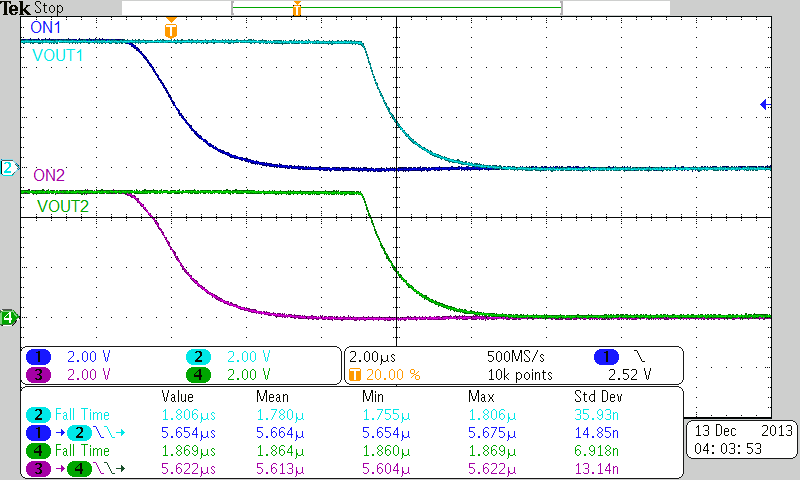
| VIN = 5 V | VBIAS = 5 V | CIN = 1 µF |
| RL = 10 Ω | CL = 0.1 µF |