ZHCSCN4F January 2014 – July 2017 TPS22968
PRODUCTION DATA.
- 1 特性
- 2 应用
- 3 说明
- 4 修订历史记录
- 5 Device Comparison
- 6 Pin Configuration and Functions
- 7 Specifications
- 8 Parameter Measurement Information
- 9 Detailed Description
- 10Application and Implementation
- 11Power Supply Recommendations
- 12Layout
- 13器件和文档支持
- 14机械、封装和可订购信息
6 Pin Configuration and Functions
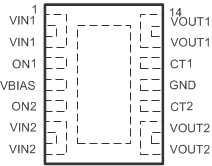
DPU PACKAGE
14-Pin WSON
Top View

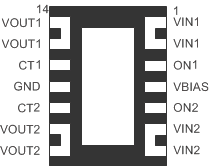
DPU PACKAGE
14-Pin WSON
Bottom View

Pin Functions
| PIN | I/O | DESCRIPTION | |
|---|---|---|---|
| NO. | NAME | ||
| 1 | VIN1 | I | Switch 1 input. Bypass this input with a ceramic capacitor to GND |
| 2 | |||
| 3 | ON1 | I | Active-high switch 1 control input. Do not leave floating |
| 4 | VBIAS | I | Bias voltage. Power supply to the device. Recommended voltage range for this pin is 2.5 V to 5.5 V. See the VIN and VBIAS Voltage Range section |
| 5 | ON2 | I | Active-high switch 2 control input. Do not leave floating |
| 6 | VIN2 | I | Switch 2 input. Bypass this input with a ceramic capacitor to GND |
| 7 | |||
| 8 | VOUT2 | O | Switch 2 output |
| 9 | |||
| 10 | CT2 | O | Switch 2 slew rate control. Can be left floating |
| 11 | GND | — | Ground |
| 12 | CT1 | O | Switch 1 slew rate control. Can be left floating |
| 13 | VOUT1 | O | Switch 2 output |
| 14 | |||
| 15 | Thermal Pad | — | Thermal pad (exposed center pad) to alleviate thermal stress. Tie to GND. See the Application Information section for layout guidelines |