ZHCSKC8 October 2019 TLV6003
PRODUCTION DATA.
8.2 Typical Application
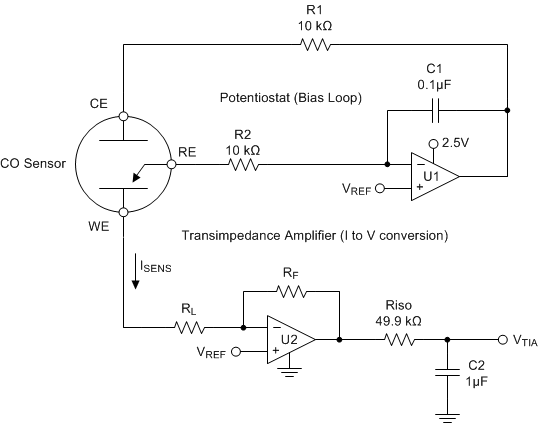
Figure 32 shows a simple micropower potentiostat circuit for use with three-terminal unbiased CO sensors; although, the design is applicable to many other type of three-terminal gas sensors or electrochemical cells.
The basic sensor has three electrodes: the sense or working electrode (WE), counter electrode (CE) and reference electrode (RE). A current flows between the CE and WE proportional to the detected concentration.
The RE monitors the potential of the internal reference point. For an unbiased sensor, the WE and RE electrodes must be maintained at the same potential by adjusting the bias on CE. Through the potentiostat circuit formed by U1, the servo feedback action maintains the RE pin at a potential set by VREF.
R1 maintains stability due to the large capacitance of the sensor.
C1 and R2 form the potentiostat integrator and set the feedback time constant.
U2 forms a transimpedance amplifier (TIA) to convert the resulting sensor current into a proportional voltage. The transimpedance gain, and resulting sensitivity, is set by RF according to Equation 1.
RL is a load resistor with a value that is normally specified by the sensor manufacturer (typically, 10 Ω). The potential at WE is set by the applied VREF.
Riso provides capacitive isolation and, combined with C2, form the output filter and ADC reservoir capacitor to drive the ADC.
 Figure 32. Three Terminal CO Gas Sensor