SLLS228G December 1995 – August 2015 TIR1000
UNLESS OTHERWISE NOTED, this document contains PRODUCTION DATA.
- 1 Features
- 2 Applications
- 3 Description
- 4 Revision History
- 5 Pin Configuration and Functions
- 6 Specifications
- 7 Detailed Description
- 8 Application and Implementation
- 9 Power Supply Recommendations
- 10Layout
- 11Device and Documentation Support
- 12Mechanical, Packaging, and Orderable Information
封装选项
机械数据 (封装 | 引脚)
散热焊盘机械数据 (封装 | 引脚)
- PS|8
订购信息
7 Detailed Description
7.1 Overview
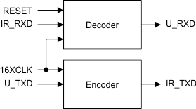
TIR1000 serial infrared (SIR) encoder and decoder is a device (CMOS) that encodes and decodes bit data according with the IrDA specifications.
For the correct performance of the TIR1000 device, an optoelectronics device and a UART device are necessary. The TIR1000 device operates as an interface between wireless infrared and UART communication.
7.2 Functional Block Diagram
7.3 Feature Description
The Infrared Data Association (IrDA) defines several protocols for sending and receiving serial infrared data, including the following rates:
- 115.2 kbps
- 0.576 Mbps
- 1.152 Mbps
- 4 Mbps
The low rate of 115.2 kbps was specified first and the others must maintain downward compatibility with it. At the 115.2 kbps rate, the protocol implemented in the hardware is fairly simple. It primarily defines a serial infrared data word to be surrounded by a start bit equal to 0 and a stop bit equal to 1. Individual bits are encoded or decoded the same whether they are start, data, or stop bits.
The TIR1000 and TIR1000I devices evaluate only single bits and follow only the 115.2-kbps protocol. The
115.2-kbps rate is a maximum rate. When both ends of the transfer are set up to a lower but matching speed, the protocol (with the TIR1000 and TIR1000I devices) still works.
The clock used to code or sample the data is 16 times the baud rate, or 1.843 MHz maximum. To code a 1, no pulse is sent or received for 1-bit time period, or 16 clock cycles. To code a 0, one pulse is sent or received within a 1-bit time period, or 16 clock cycles. The pulse must be at least 1.6 μs wide and 3 clock cycles long at 1.843 MHz. At lower baud rates, the pulse can be 1.6 μs wide or as long as 3 clock cycles.
The transmitter output, IR_TXD, is intended to drive an LED circuit to generate an infrared pulse. The LED circuits work on positive pulses. A terminal circuit is expected to create the receiver input, IR_RXD. Most (but not all) PIN circuits have inversion and generate negative pulses from the detected infrared light. Their output is normally high. The TIR1000 and TIR1000I devices can decode either negative or positive pulses on IR_RXD.
7.4 Device Functional Modes
7.4.1 IrDA Encoder Function
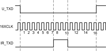
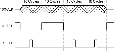
Serial data from a UART is encoded to transmit data to the optoelectronics. While the serial data input to this block (U_TXD) is high, the output (IR_TXD) is always low, and the counter used to form a pulse on IR_TXD is continuously cleared. After U_TXD resets to 0, IR_TXD rises on the falling edge of the seventh 16XCLK. On the falling edge of the tenth 16XCLK pulse, IR_TXD falls, creating a 3-clock-wide pulse. While U_TXD stays low, a pulse is transmitted during the seventh to tenth clocks of each 16-clock bit cycle.
Detailed Timing Diagram
Macro View
7.4.2 IrDA Decoder Function
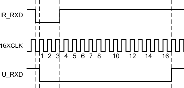
After reset, U_RXD is high and the 4-bit counter is cleared. When a falling edge is detected on IR_RXD, U_RXD falls on the next rising edge of 16XCLK with sufficient setup time. U_RXD stays low for 16 cycles (16XCLK) and then returns to high as required by the IrDA specification. As long as no pulses (falling edges) are detected on IR_RXD, U_RXD remains high.
Detailed Timing Diagram

Macro View
It is possible for jitter or slight frequency differences to cause the next falling edge on IR_RXD to be missed for one 16XCLK cycle. In that case, a 1-clock-wide pulse appears on U_RXD between consecutive zeroes. It is important for the UART to strobe U_RXD in the middle of the bit time to avoid latching this 1-clock-wide pulse. The TL16C550C UART already strobes incoming serial data at the proper time. Otherwise, note that data is required to be framed by a leading zero and a trailing one. The falling edge of that first zero on U_RXD synchronizes the read strobe. The strobe occurs on the eighth 16XCLK pulse after the U_RXD falling edge and once every 16 cycles thereafter until the stop bit occurs.
 Figure 6. Timing Causing 1-Clock-Wide Pulse Between Consecutive Ones
The TIR1000 and TIR1000I can decode positive pulses on IR_RXD. The timing is different, but the variation is invisible to the UART. The decoder, which works from the falling edge, now recognizes a zero on the trailing edge of the pulse rather than on the leading edge. As long as the pulse width is fairly constant, as defined by the specification, the trailing edges should also be 16 clock cycles apart and data can readily be decoded. The zero appears on U_RXD after the pulse rather than at the start of it.
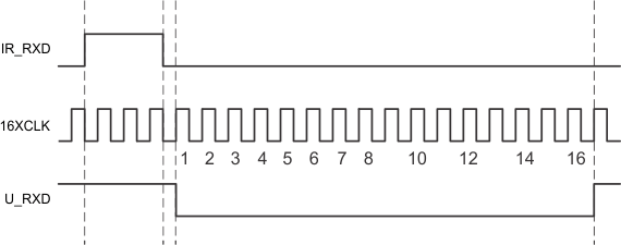
Detailed View
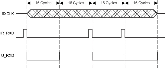
Macro View