SLLS228G December 1995 – August 2015 TIR1000
UNLESS OTHERWISE NOTED, this document contains PRODUCTION DATA.
- 1 Features
- 2 Applications
- 3 Description
- 4 Revision History
- 5 Pin Configuration and Functions
- 6 Specifications
- 7 Detailed Description
- 8 Application and Implementation
- 9 Power Supply Recommendations
- 10Layout
- 11Device and Documentation Support
- 12Mechanical, Packaging, and Orderable Information
封装选项
机械数据 (封装 | 引脚)
散热焊盘机械数据 (封装 | 引脚)
- PS|8
订购信息
8 Application and Implementation
NOTE
Information in the following applications sections is not part of the TI component specification, and TI does not warrant its accuracy or completeness. TI’s customers are responsible for determining suitability of components for their purposes. Customers should validate and test their design implementation to confirm system functionality.
8.1 Application Information
IrDA provides several specifications for a complete set of protocols for wireless infrared communications.
8.2 Typical Application
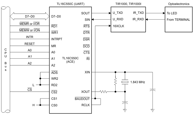
A simple application of the TIR1000 device is developing a system with an optoelectronics device and a UART device (TL16C500C). Hence, the TIR1000 device interfaces between the infrared and serial devices.
 Figure 9. Typical Application Schematic
8.2.1 Design Requirements
Table 1 lists the design requirements for the typical application.
Table 1. Design Requirements
| DESIGN PARAMETER | EXAMPLE VALUE |
|---|---|
| Power supply | 3 V (low voltage) |
| 1.843-MHz clock source | Crystal |
| Baud rate | 115.2 kbps |
| TRANSMITTER | |
| Peak wavelength | 850–900 nm |
| Intensity in angular range | 40–500 mW/Sr |
| Half angle | ±15-30° |
| Pulse Duration at 115.2 kbps | 2.23 µs |
| RECEIVER | |
| Irradiance in angular range | 4–500 mW/cm2 |
| Half angle | ±15° |
| Receiver latency | 10 ms |
8.2.2 Detailed Design Procedure
The asynchronous communications element (TL16C550C) contains a programmable baud generator that takes a clock input in the range between DC and 16 MHz and divides it by a divisor in the range between
1 and (216 – 1). The output frequency of the baud generator is sixteen times (16×) the baud rate. The formula for the divisor is shown in Equation 1.
For example:
Error (divisor) <1%
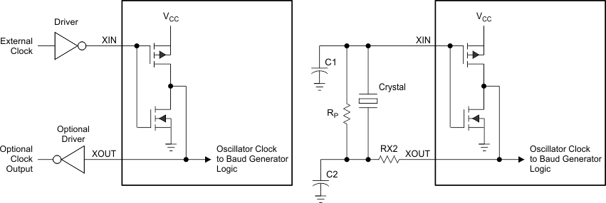
 Figure 10. Typical Clock Circuits (Programmable Baud Generator)
Table 2. Typical Crystal Oscillator Network
| CRYSTAL | Rp | RX2 | C1 | C2 |
|---|---|---|---|---|
| 1.8432 MHz | 1 MΩ | 1.5 kΩ | 10–30 pF | 40–60 pF |
8.2.3 Application Curves

