ZHCSI92D May   2018  – November 2020 TAS5805M

PRODUCTION DATA  

  1. 特性
  2. 应用
  3. 说明
  4. Revision History
  5. Device Comparison Table
  6. Pin Configuration and Functions
  7. Specifications
    1. 6.1 Absolute Maximum Ratings
    2. 6.2 ESD Ratings
    3. 6.3 Recommended Operating Conditions
    4. 6.4 Thermal Information
    5. 6.5 Electrical Characteristics
    6. 6.6 Timing Requirements
    7. 6.7 Typical Characteristics
      1. 6.7.1 Bridge Tied Load (BTL) Configuration Curves with 1SPW Mode
      2. 6.7.2 Bridge Tied Load (BTL) Configuration Curves with BD Mode
      3. 6.7.3 Bridge Tied Load (BTL) Configuration Curves with Ferrite Bead + Capacitor as the Output Filter
      4. 6.7.4 Parallel Bridge Tied Load (PBTL) Configuration with 1SPW Modulation
      5. 6.7.5 Parallel Bridge Tied Load (PBTL) Configuration with BD Modulation
  8. Parameter Measurement Information
  9. Detailed Description
    1. 7.1 Overview
    2. 7.2 Functional Block Diagram
    3. 7.3 Feature Description
      1. 7.3.1 Power Supplies
      2. 7.3.2 Device Clocking
      3. 7.3.3 Serial Audio Port – Clock Rates
      4. 7.3.4 Clock Halt Auto-recovery
      5. 7.3.5 Sample Rate on the Fly Change
      6. 7.3.6 Serial Audio Port - Data Formats and Bit Depths
      7. 7.3.7 Digital Audio Processing
      8. 7.3.8 Class D Audio Amplifier
        1. 7.3.8.1 Speaker Amplifier Gain Select
        2. 7.3.8.2 Class D Loop Bandwidth and Switching Frequency Setting
    4. 7.4 Device Functional Modes
      1. 7.4.1 Software Control
      2. 7.4.2 Speaker Amplifier Operating Modes
        1. 7.4.2.1 BTL Mode
        2. 7.4.2.2 PBTL Mode
      3. 7.4.3 Low EMI Modes
        1. 7.4.3.1 Spread Spectrum
        2. 7.4.3.2 Channel to Channel Phase Shift
        3. 7.4.3.3 Multi-Devices PWM Phase Synchronization
      4. 7.4.4 Thermal Foldback
      5. 7.4.5 Device State Control
      6. 7.4.6 Device Modulation
        1. 7.4.6.1 BD Modulation
        2. 7.4.6.2 1SPW Modulation
        3. 7.4.6.3 Hybrid Modulation
    5. 7.5 Programming and Control
      1. 7.5.1 I2 C Serial Communication Bus
      2. 7.5.2 Slave Address
        1. 7.5.2.1 Random Write
        2. 7.5.2.2 Sequential Write
        3. 7.5.2.3 Random Read
        4. 7.5.2.4 Sequential Read
        5. 7.5.2.5 DSP Memory Book, Page and BQ Coefficients Update
        6. 7.5.2.6 Example Use
        7. 7.5.2.7 Checksum
          1. 7.5.2.7.1 Cyclic Redundancy Check (CRC) Checksum
          2. 7.5.2.7.2 Exclusive or (XOR) Checksum
      3. 7.5.3 Control via Software
        1. 7.5.3.1 Startup Procedures
        2. 7.5.3.2 Shutdown Procedures
        3. 7.5.3.3 Protection and Monitoring
          1. 7.5.3.3.1 Overcurrent Shutdown (OCSD)
          2. 7.5.3.3.2 Speaker DC Protection
          3. 7.5.3.3.3 Device Over Temperature Protection
          4. 7.5.3.3.4 Device Over Voltage/Under Voltage Protection
            1. 7.5.3.3.4.1 Over Voltage Protection
            2. 7.5.3.3.4.2 Under Voltage Protection
          5. 7.5.3.3.5 Clock Fault
    6. 7.6 Register Maps
      1. 7.6.1 CONTROL PORT Registers
  10. Application and Implementation
    1. 8.1 Application Information
      1. 8.1.1 Bootstrap Capacitors
      2. 8.1.2 Inductor Selections
      3. 8.1.3 Power Supply Decoupling
      4. 8.1.4 Output EMI Filtering
    2. 8.2 Typical Applications
      1. 8.2.1 2.0 (Stereo BTL) System
        1. 8.2.1.1 Design Requirements
        2. 8.2.1.2 Detailed Design Procedures
          1. 8.2.1.2.1 Step 1: Hardware Integration
          2. 8.2.1.2.2 Step 2: Speaker Tuning
          3. 8.2.1.2.3 Step 3: Software Integration
        3. 8.2.1.3 Application Curves
          1. 8.2.1.3.1 Audio Performance
          2. 8.2.1.3.2 EN55022 Conducted Emissions Results with Ferrite Bead as output filter
          3. 8.2.1.3.3 EN55022 Radiated Emissions Results with Ferrite Bead as output filter
      2. 8.2.2 MONO (PBTL) Systems
        1. 8.2.2.1 Design Requirements
        2. 8.2.2.2 Detailed Design Procedure
        3. 8.2.2.3 Application Curves
      3. 8.2.3 Advanced 2.1 System (Two TAS5805M Devices)
  11. Power Supply Recommendations
    1. 9.1 DVDD Supply
    2. 9.2 PVDD Supply
  12. Layout
    1. 9.1 Layout Guidelines
      1. 9.1.1 General Guidelines for Audio Amplifiers
      2. 9.1.2 Importance of PVDD Bypass Capacitor Placement on PVDD Network
      3. 9.1.3 Optimizing Thermal Performance
        1. 9.1.3.1 Device, Copper, and Component Layout
        2. 9.1.3.2 Stencil Pattern
          1. 9.1.3.2.1 PCB footprint and Via Arrangement
          2. 9.1.3.2.2 Solder Stencil
    2. 9.2 Layout Example
  13. 10Device and Documentation Support
    1. 10.1 Device Support
      1. 10.1.1 Device Nomenclature
      2. 10.1.2 Development Support
    2. 10.2 Receiving Notification of Documentation Updates
    3. 10.3 支持资源
    4. 10.4 Trademarks
    5. 10.5 静电放电警告
    6. 10.6 术语表
  14. 11Mechanical, Packaging, and Orderable Information

封装选项

请参考 PDF 数据表获取器件具体的封装图。

机械数据 (封装 | 引脚)
  • PWP|28
散热焊盘机械数据 (封装 | 引脚)
订购信息

说明

TAS5805M 是一款高效立体声闭环 D 类放大器,可提供具有低功率耗散和丰富声音的低成本数字输入解决方案。该器件的集成音频处理器和 96kHz 架构支持高级音频处理流程(包括 SRC、每通道 15 个 BQ、音量控制、音频混合、3 频带 4 阶 DRC、全频带 AGL、THD 管理器和电平计)。

TAS5805M 采用 TI 的专有混合调制方案,消耗超低的静态电流(13.5V PVDD 下为 16.5mA),从而能够延长便携式音频应用中的电池寿命。凭借先进的 EMI 抑制技术,设计人员可以利用廉价的铁氧体磁珠滤波器来减小布板空间并降低系统成本。

器件信息
器件型号封装(1)封装尺寸(标称值)
TAS5805MTSSOP (28) PWP9.7mm × 4.4mm
如需了解所有可用封装,请参阅产品说明书末尾的可订购产品附录。
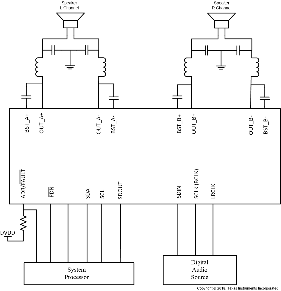
GUID-F64B14EC-8047-4F8F-A330-C7B1A2B49DE1-low.gif简化版方框图